2
Bosch Security Systems | 04-2003 | 3922 988 43318 en
Digital Congress Network | Installation and Operating Manual | Chapter 2 - Contribution Equipment
en | 2-25
LBB 4157/00 Chip Card Encoder
2.20 LBB 4157/00 Chip Card Encoder
Supporting a wide range of micro-processor cards compliant with ISO standards as well as the most
frequently used synchronous cards, the LBB 4157 Chip Card encoder can easily be
integrated into the DCN system.
The LBB 4157/00 is delivered with an external installation kit, and is powered by the workstation to
which it is connected by a serial port.
The encoder is used in combination with DCN’s ID Card Encoder Software package LBB 3581/00.
The software can detect whether a Chip Card encoder or Magnetic stripe card encoder is connected.
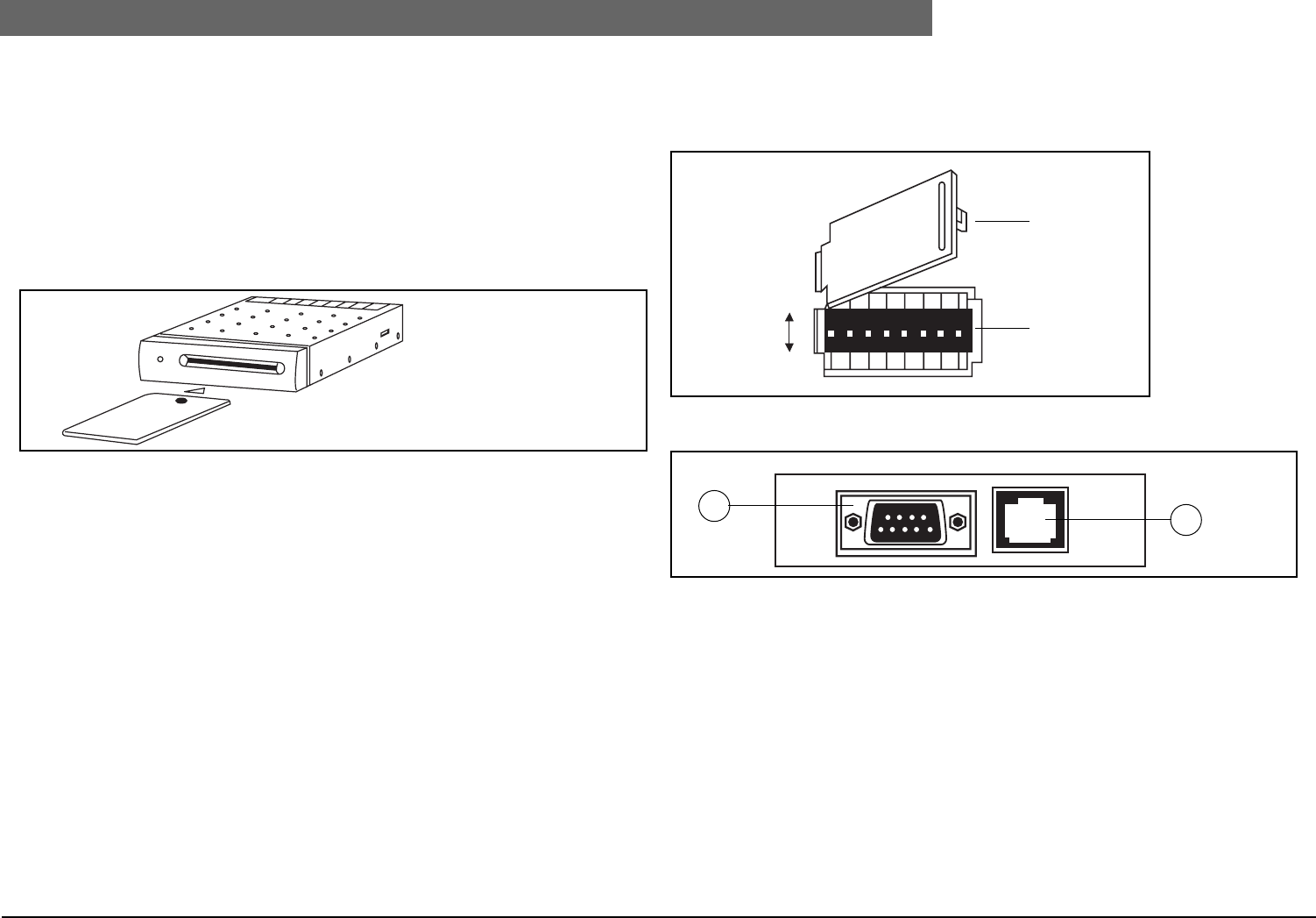
FIG. 2-40 LBB 4157/00 Chip Card Encoder
Technical specification
Chip Card Interface: - 8-contact friction connector (ISO location)
- Protection against unexpected card withdrawal, short circuits and over
consumption
Serial Interface: - RS232 interface to the DCN PC on RJ45 connector (connector 2)
- RS232 interface on DB9 connector reserved for future use
(connector 1)
Internal architecture: - 8-bit microcontroller
- 128-Kbyte OTP memory
- 32-Kbyte static RAM
Power consumption: - 200 mA maximum on 5V
Compliance: The LBB 4157/00 complies with the following security and
EMC directives and international standards:
- 73/23/CEE, ISO/IEC 7816-1/2/3 and CEM 89/336/CEE, modified by the
92/31/CEE directive.
- EN 55022 Class B, EN 60950 and EN 50082-1, provided that cables
supplied by BOSCH and an EC-certified computer are used.
The Chip Card Encoder is a SELV (Safety Extra Low Voltage) equipment and must be connected to a
PC of the same kind.
2.20.1 Position of the DIP switches
• Open the DIP compartment under the encoder by lifting the lid.
• Using a sharp object such as a pencil, set all the DIPs to the OFF position (see below)
FIG. 2-41 Bottom view DIP compartment
FIG. 2-42 Rear view of the Chip card encoder
ON
87654321
ON
OFF
DIP switches
Lid
1
2


