2
Bosch Security Systems | 04-2003 | 3922 988 43318 en
Digital Congress Network | Installation and Operating Manual | Chapter 8 - Information Displays
en | 8-2
LBB 3512/00 Data Distribution Board
Electrical requirements
• Supply voltage (optional):10 - 40 V d.c.
• Current consumption:< 50 mA @ 40 V
The Data Communication board includes a 10-pole and two 20-pole ‘Micromatch’ flat-cable
connectors (female) and a 9-pin D-type connector (male) for serial data output.
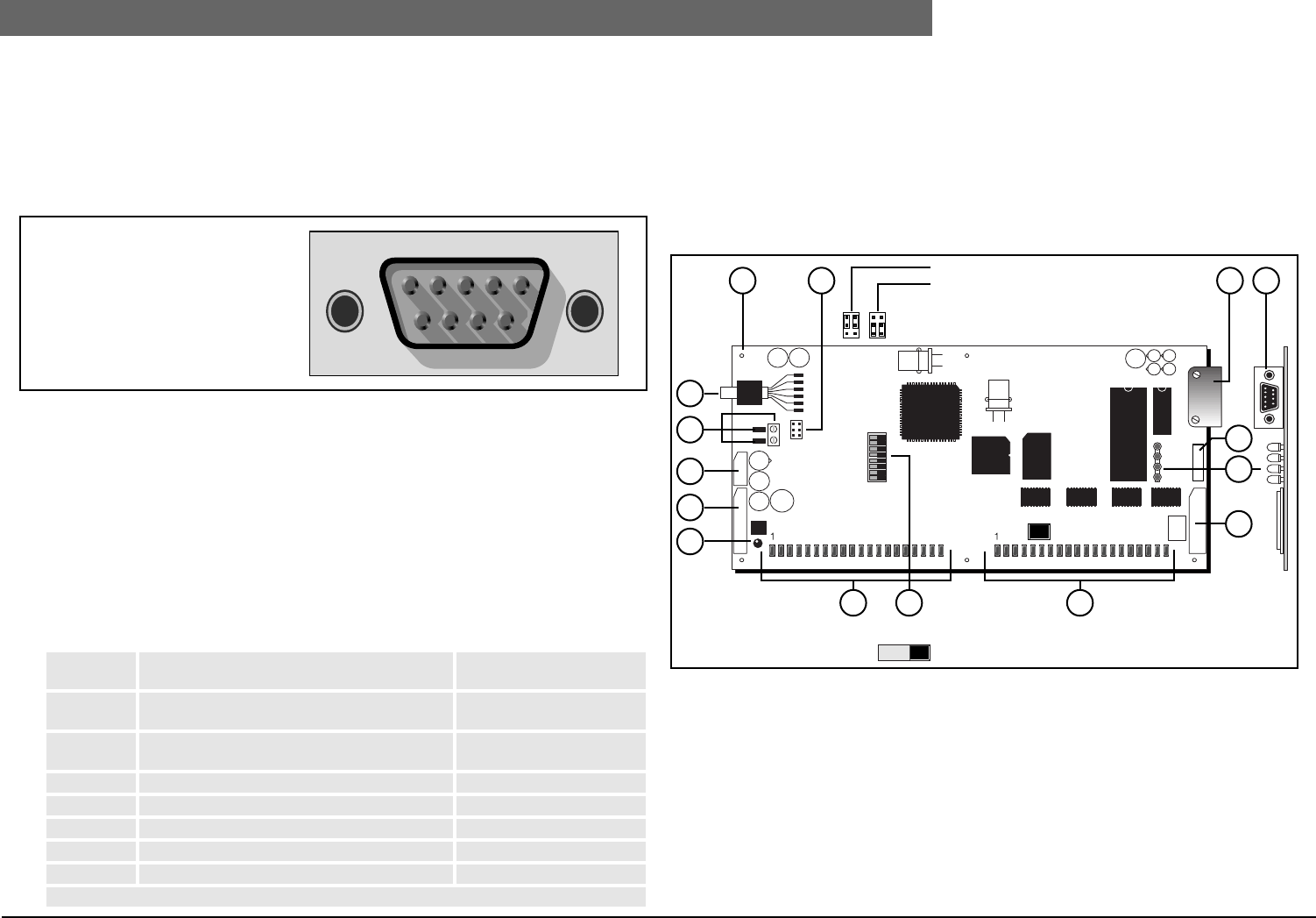
The pin configuration is of the D-type is shown below:
FIG 8-3 Data Distribution Board 9-pin Sub-D connector
Connectors, Controls and Indicators (see FIG 8-4)
1. 6 x 3.5 mm (0.13 in) mounting holes.
2. 2 x jumpers to select between either the DCN system power supply or an external power sup-
ply.
3. 9-pole Sub-D connector (male) for RS232 communication.
4. 4 x LED indicators for test purposes.
5. Parallel input connector 20-pole Micro-Match connector.
6. Parallel input connector via 20 solder pads.
7. Connector for test purposes.
8. 8-pole dip switch for communication mode and function setting as follows:
9. Parallel output connector via 20 solder pads (open collector outputs).
10. Initialization button with LED indicator to indicate the none initialized mode.
11. Parallel output connector 20-pole Micro-Match connector.
12. 10-pole Micro-Match connector for the external power supply. Initialization status output and
initialization button.
13. 2-pole external power supply connector (2-solder pads) and a 2-pole screw connector.
14. 2 m (6.5 ft.) long cable terminated with a 6-pole circular connector for connection to the DCN
trunk-line.
FIG 8-4 Layout Data Distribution Board
Parts delivered with LBB 3512/00
• 2 x Micromatch connector 2x10-pole2-215083-0 AMP
• 1 x Micromatch connector 2x5-pole1-215083-0 AMP
• 1 x Bus connectorSOURIAU DE 09 S 067HT
• 2 x Screw retainer167500-1 AMP
• 1 x Cable clamp 9-poleAMP 207467-1
DP1 RS232 uplink transfer disabled/enabled OFF - Disabled
ON - Enabled
DP2 Passive or active mode setting OFF - Passive
ON - Active
DP3 Baudrate for RS232 communication OFF - 9600 Baud (default)
ON - 19200 Baud
DP4 Reserved -
DP5 Reserved -
DP6* Passive mode, Least Significant address bit 0 OFF - 0, ON - 1
DP7* Passive mode address bit 1 OFF - 0, ON - 1
DP8* Passive mode most significant address bit 2 OFF - 0, ON - 1
*See board address settings.
15432
6987
PIN 1 Not connected
PIN 2 RxD
PIN 3 TxD
PIN 4 Not connected
PIN 5 Signal ground
PIN 6 Not connected
PIN 7 RTS
PIN 8 CTS
PIN 9 Not connected
1
1
8
1 2
DCN system supply
Ext. power supply
14
13
12
10
11
9 8 6
5
4
7
3 3
DIP-switch
OFF ON
Dimensions (h x w): 100 x 200 mm (3.93 x 7.87”)


