


II-24
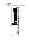
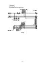
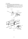
1.4 Panel Sensor PCB
The following parts are on the panel sensor.
• Control Panel........... 1 Switch, 4 lamps
• Connector ................Low-voltage, high-voltage, solenoid, main motor, toner sensor,
laser, polygon motor, connector for main PCB
• Registration sensor
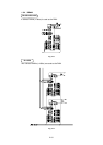
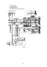
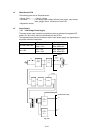
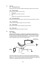
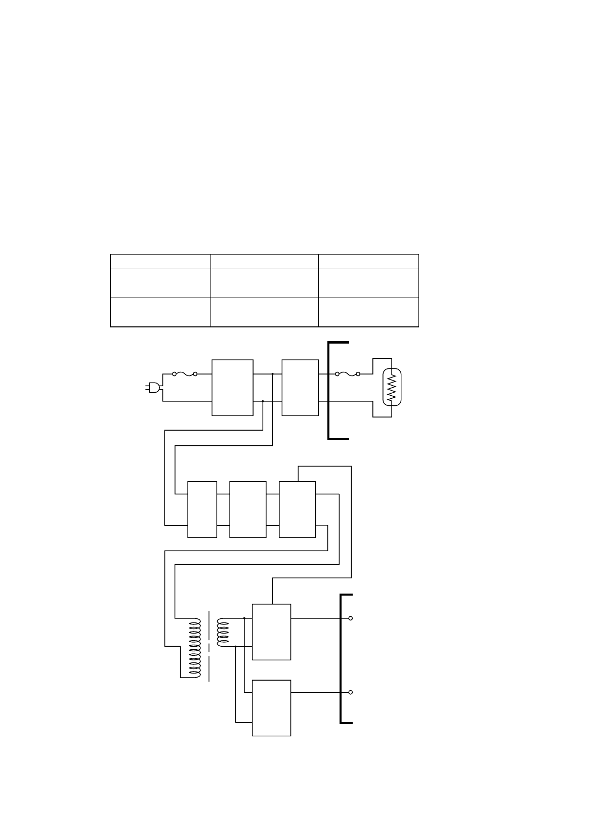
1.5 Power Supply
1.5.1 Low-voltage Power Supply
The power supply uses a switching regulation system to generate the regulated DC
power (+5V and +24V), which are converted from the AC line.
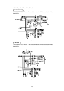
The regulated output and the production code of each power supply vary depending on
the printer model as listed below;
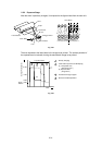
Model Regulated Output Production Code
HL-820/1020/1040
+5V / 0.6 A
+24V / 2.0 A
100V: MPW1547
200V: MPW1447
HL-1050
+5V / 1.2A
+24V / 2.0A
100V: MPW1550
200V: MPW1450
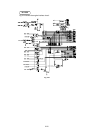
Heater
Circuit
Thermal
Fuse
Lightning
Surge
Absorber
Feedback
Line
Filter
Fuse
Rectifier Oscillator
24V
Regulation
Circuit
5V
Regulation
Circuit
24V
5V
Lamp
(Heater)
(Panel Sensor Circuit)
Fig. 2-27