


III-12
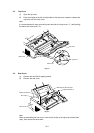
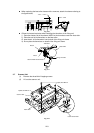
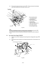
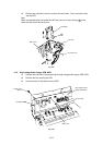
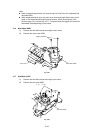
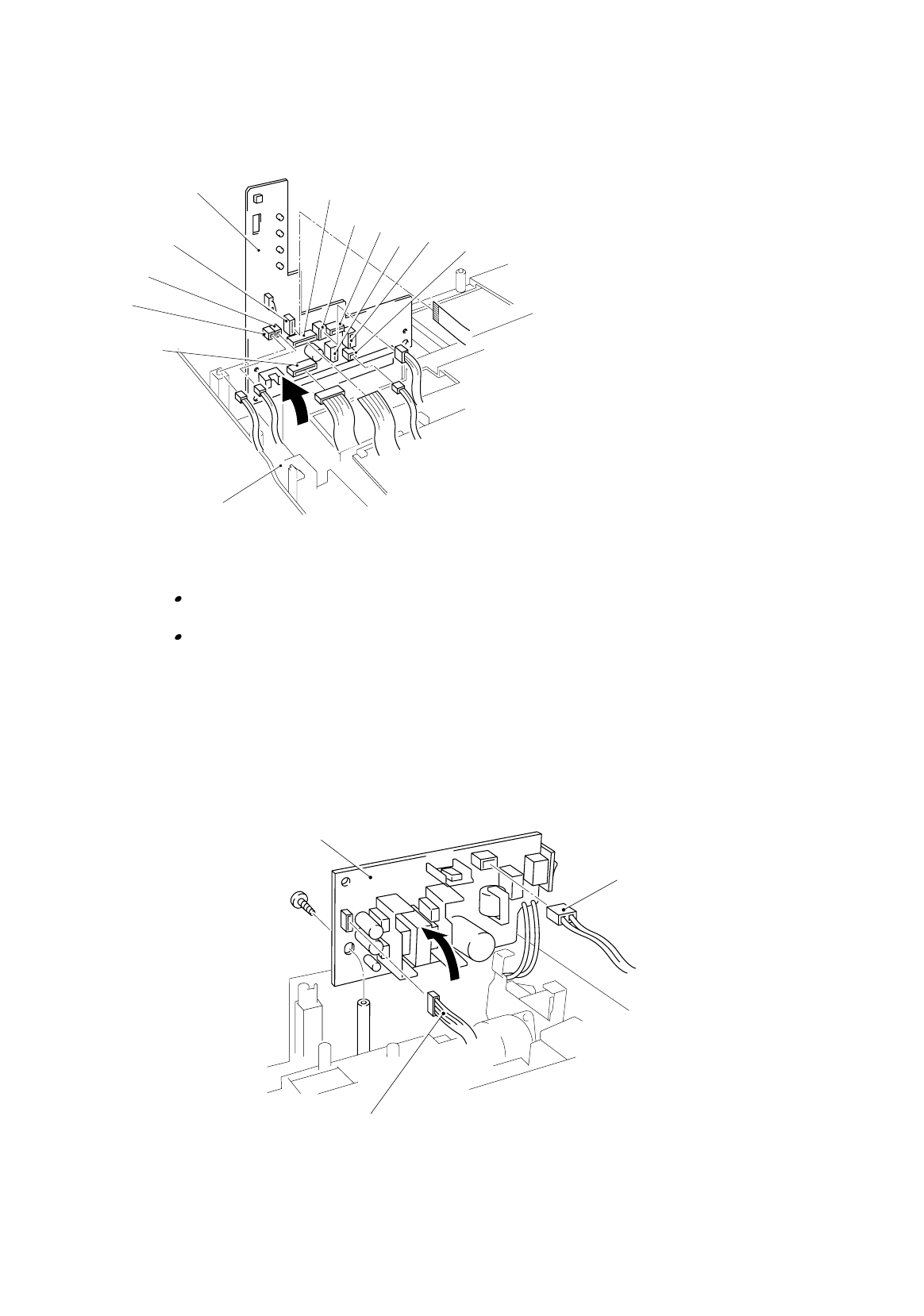
(3) Disconnect the eight connectors from the PCB. (Three connectors have already
been disconnected when removing the scanner unit.)
1
2
3
4
5
6
7
8
9
10
(Name of the Harnesses)
1. Low-voltage harness
2. Erase lamp harness
3. Toner harness
4. Scan motor flat cable
5. Laser harness
6. Solenoid harness
7. Main / sub motor connector
8. Fan motor 1 harness
9. Fan motor 2 harness
10. High-voltage flat cable
Fig. 3-19
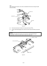
Note:
When re-assembling, the cable connectors must be inserted securely into the PCB
connectors and the PCB must not be stressed by the harnesses.
The connectors should be inserted by matching the housing color and the number of
pins.
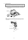
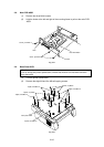
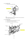
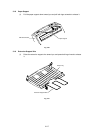
3.11 Low-voltage Power Supply PCB ASSY
(1) Remove the one M4x12 tapping screw securing the low-voltage power supply PCB
ASSY.
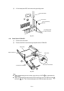
(2) Disconnect the two connectors for the heater harness and the LV harness from the
PCB.
Fig. 3-20
Panel Sensor
PCB ASSY
Main frame
LV harness
Low-voltage Power Supply ASSY
Hr hrn