


III-13
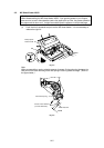
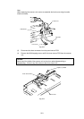
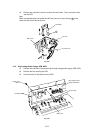
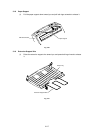
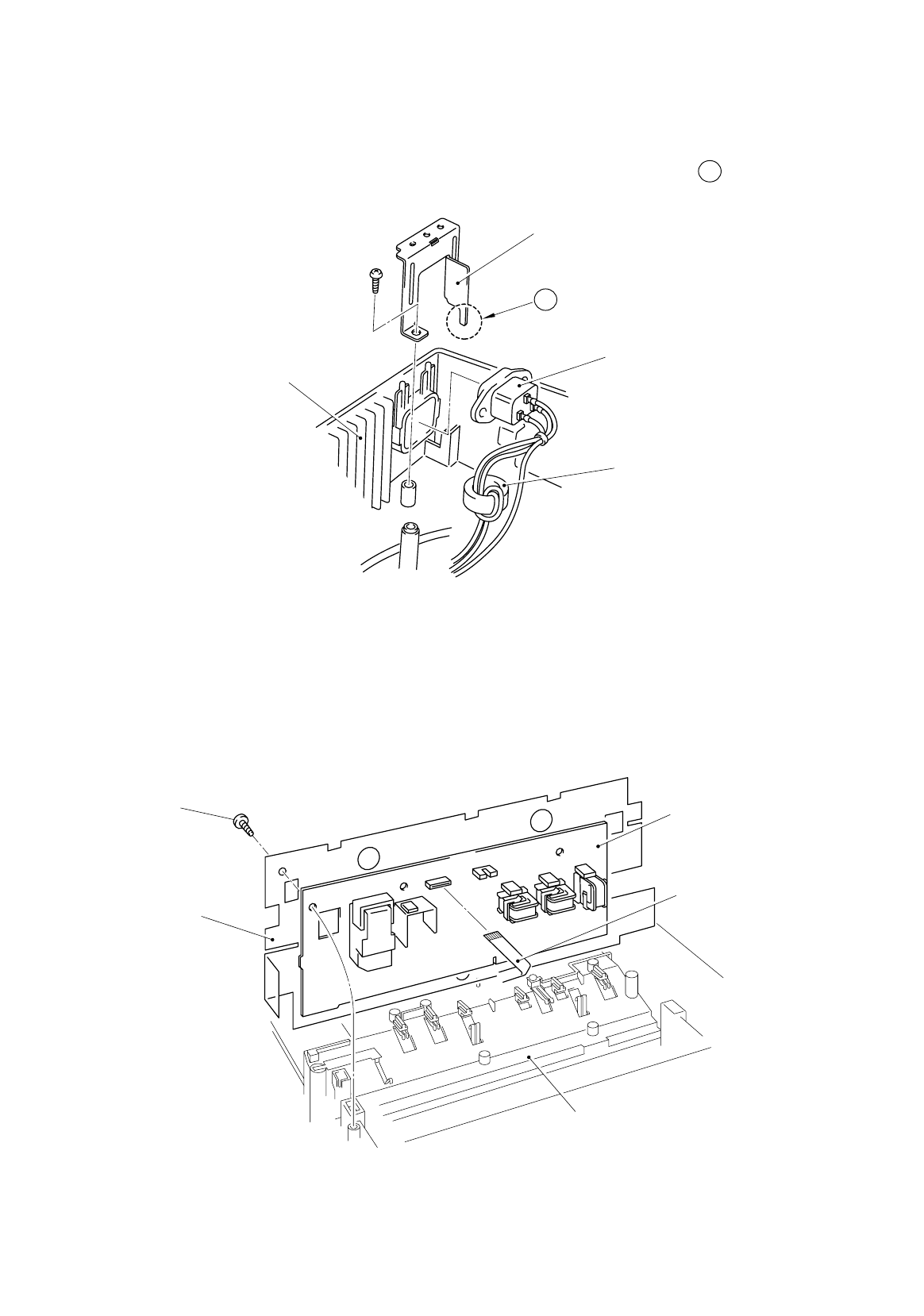
(3) Remove the one M4x12 screw to remove the inlet holder. Then, remove the inlet
and the PCB.
Note:
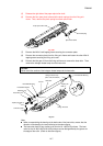
When re-assembling the inlet holder and AC inlet, be sure to insert the part A of the
holder into the hole of the ferrite core.
Fig. 3-21
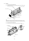
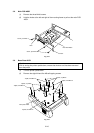
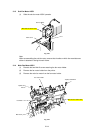
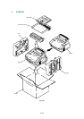
3.12 High-voltage Power Supply PCB ASSY
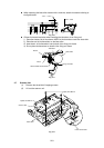
(1) Remove the one M4x12 screw securing the high-voltage power supply PCB ASSY.
(2) Remove the film covering the PCB.
(2) Disconnect the HV flat cable from the PCB.
Fig. 3-22
Taptite, bind
M4x12
Main Cover
HV flat cable
High-voltage Power
Supply PCB ASSY
Inlet Holder
AC Inlet
Main Cover
Insulation Sheet
Ferrite Core
A