


i
ii
CHAPTER IV MAINTENANCE AND TROUBLESHOOTING.......................... IV-1
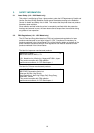
1. INTRODUCTION ..............................................................................................................IV-1
1.1 Initial Check........................................................................................................................IV-1
1.2 Basic Procedure.................................................................................................................IV-2
2. CONSUMABLE PARTS....................................................................................................IV-3
2.1 Drum Unit...........................................................................................................................IV-3
2.2 Toner Cartridge ..................................................................................................................IV-3
2.3 Periodical Replacement Parts.............................................................................................IV-3
3. IMAGE DEFECTS ............................................................................................................IV-4
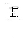
3.1 Image Defect Examples .....................................................................................................IV-4
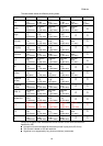
3.2 Troubleshooting Image Defects ..........................................................................................IV-5
3.3 Location of High-voltage Contacts and Grounding Contacts.............................................. IV-19
3.4 Location of Feed Roller Shaft and Grounding Contacts..................................................... IV-20
4. PAPER JAM ...................................................................................................................IV-21
5. TROUBLESHOOTING MALFUNCTIONS.......................................................................IV-22
6. INSPECTION MODE ......................................................................................................IV-27
6.1 Incorporated Inspection Modes......................................................................................... IV-27
6.2 Error Codes......................................................................................................................IV-29
APPENDICES
1. Serial No. Descriptions ......................................................................................................A-1
2. Connection Diagram, HL-820/1020 ...................................................................................A-2
3. Connection Diagram, HL-1040 ..........................................................................................A-3
4. Connection Diagram, HL-1050 ..........................................................................................A-4
5. Main PCB Circuit Diagram, (HL-820/1020/1040), (1/2)......................................................A-5
6. Main PCB Circuit Diagram, (HL-820/1020/1040), (2/2)......................................................A-6
7. Main PCB Circuit Diagram, (HL-1050), (1/5)......................................................................A-7
8. Main PCB Circuit Diagram, (HL-1050), (2/5)......................................................................A-8
9. Main PCB Circuit Diagram, (HL-1050), (3/5)......................................................................A-9
10. Main PCB Circuit Diagram, (HL-1050), (4/5)....................................................................A-10
11. Main PCB Circuit Diagram, (HL-1050), (5/5)....................................................................A-11
12. Panel Sensor PCB Circuit Diagram .................................................................................A-12
13. Low-voltage Power Supply PCB Circuit Diagram, HL-820/1020/1040 (110 - 120V)........A-13
14. Low-voltage Power Supply PCB Circuit Diagram, HL-820/1020/1040 (220 - 240V)........A-14
15. Low-voltage Power Supply PCB Circuit Diagram, HL-1050 (110 - 120V)........................A-15
16. Low-voltage Power Supply PCB Circuit Diagram, HL-1050 (220 - 240V)........................A-16
17. High-voltage Power Supply PCB Circuit Diagram............................................................A-17
18. How to Know Drum Unit Life & Page Counter .................................................................A-18
19. Diameter / Circumference of Rollers................................................................................A-20