


III-9
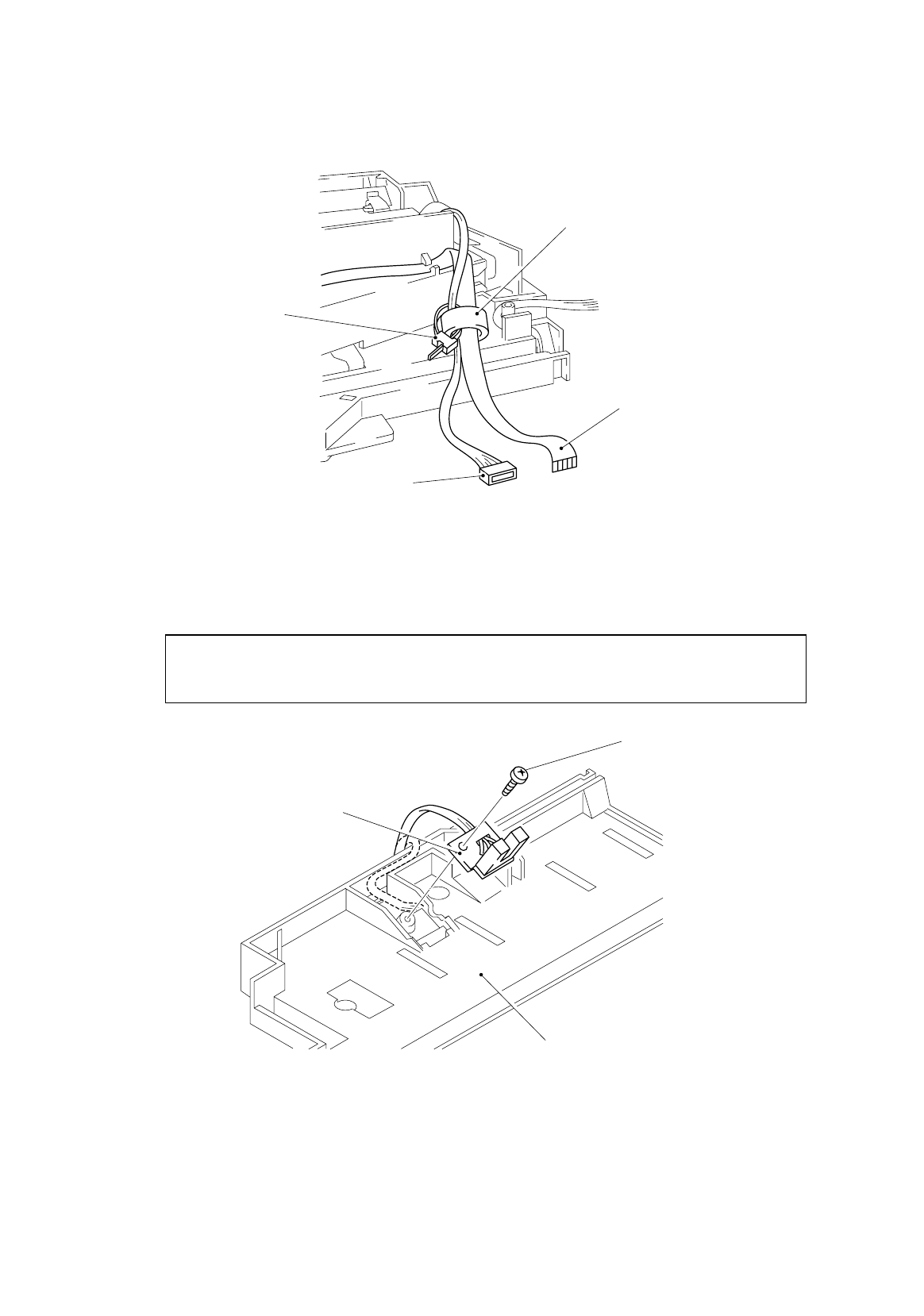
Note:
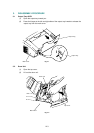
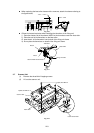
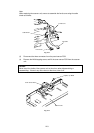
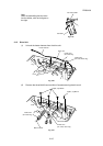
When replacing the scanner unit, ensure to assemble the ferrite core using the cable
binder as follows;
Fig. 3-13
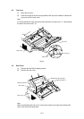
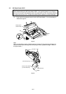
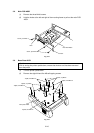
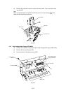
(3) Disconnect the three connectors from the panel sensor PCB.
(4) Remove the M3x8 tapping screw, and lift the toner sensor PCB from the scanner
unit.
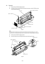
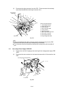
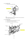
Caution:
Never touch the inside of the scanner unit or the mirror when disassembling or
reassembling. If there is any dirt or dust on the mirror, blow it off.
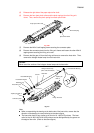
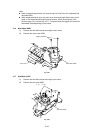
Fig. 3-14
Toner Sensor PCB
Scanner Unit
Taptite, cup M3x8
Ferrite Core
Flat cable
Cable binder
LD harness