


III-6
3.6 Fixing Unit
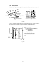
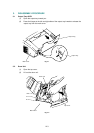
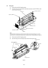
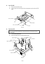
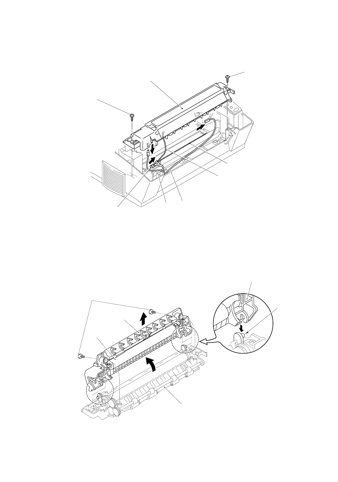
(1) Remove the two M4x16 tapping screws.
(2) Lifting the fixing unit, disconnect the thermistor connector on the EL PCB first, then
the two heater harnesses.
Fig. 3-7
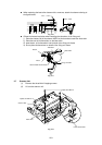
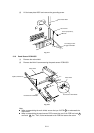
Note:
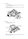
The eject sensor actuator may also be removed when removing the fixing unit. In this
case be sure to re-assemble the eject sensor actuator when re-assembling the fixing unit.
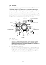
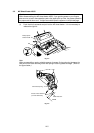
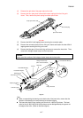
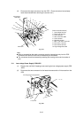
(3) Remove the two M3x12 tapping screws.
(4) Open the fixing unit cover along the open side of the fixing unit cover.
Fig. 3-8
Taptite, bind M3x12
Fixing unit cover
Shaft
Fixing unit
vr
Pressure roller
Fixin
g
unit frame
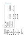
Fixing Unit
Taptite, cup M4x16
Thermistor connector
Heater harness (Brown)
Thermistor harness
EL PCB
Taptite, cup M4x16
Heater harness
(Blue)