


III-7
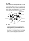
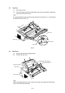
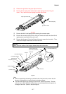
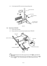
(5) Release the right side of the paper eject roller shaft.
(6) Remove the four eject pinch rollers and the pinch springs from the fixing unit
frame. Then, remove the pinch spring from each pinch roller.
Fig. 3-8a
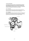
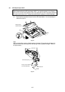
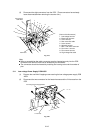
(7) Remove the M3x10 self tapping screw securing the connector plate.
(8) Remove the connector plate from the fixing unit frame and loosen the other M3x10
tapping screw securing the fixing unit cover.
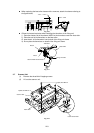
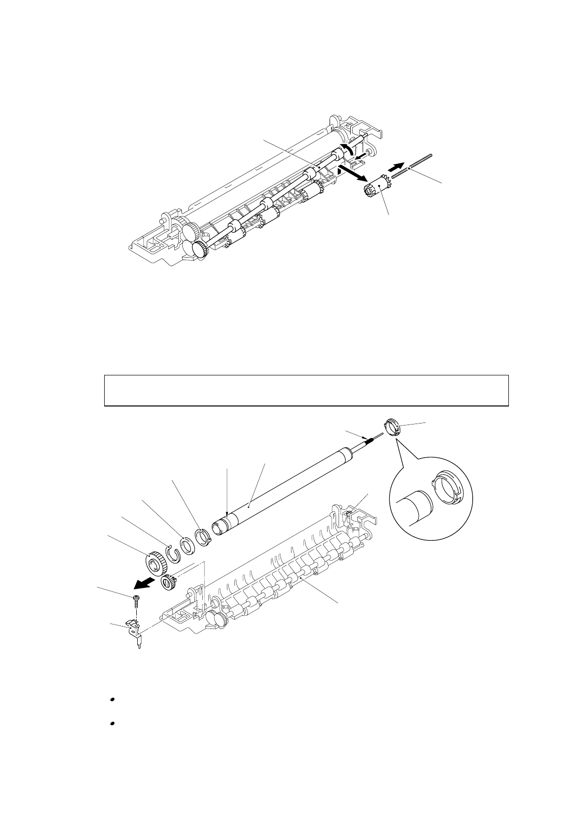
(9) Remove the idle gear 16 from the fixing unit frame to remove the heat roller. Then,
remove the halogen heater lamp from the heat roller.
Caution :
Never touch the surface of the halogen heater lamp and the heat roller.
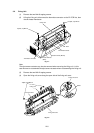
Fig. 3-9
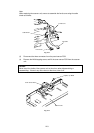
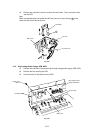
Note:
When re-assembling the bearing at the both ends of the heat roller, ensure that the
direction of the bearing is correct referring to the above figure.
The heat roller itself is very similar to the one for HL-1060/1070 printers. The heat
roller for the HL-820/1020/1040/1050 printers can be distinguished by the groove on
the edge of the roller. (Refer to the above figure.)
Halogen heater lamp
(Blue 100V, Red 200V)
Heat roller
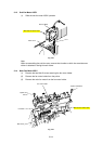
Taptite, pan M3x10
Connector plate
Fixing unit frame
Idle gear 16
Taptite, pan
M3x10
Heat roller gear
Heat Roller Bearing
Heat Roller Washer
Retaining ring
Groove
Heat Roller Bearing
PR98292
Paper eject roller shaft
Pinch Spring
E
j
ect Pinch Roller