


58
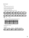
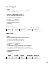
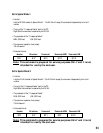
Mark Duration period
Min. Max.
T1 - 300ms
T2 0ms 200ms
T3 10ms T4-T2
T4 10ms *1
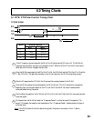
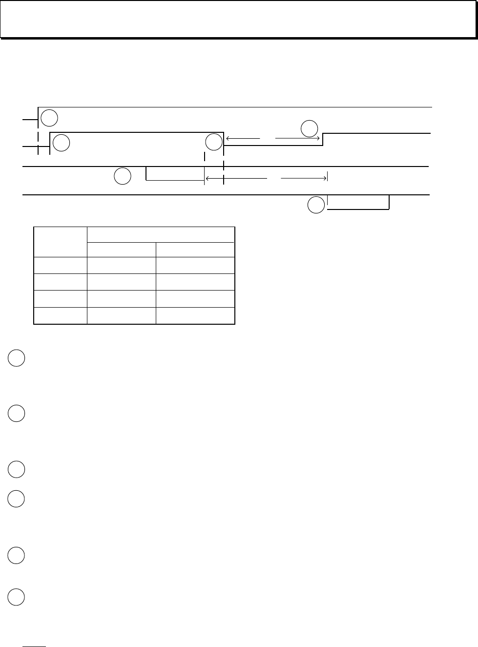
6.1 RTS/CTS Flow Control Timing Chart
PC SIDE SIGNAL
Command
C-Response
RTS
T1
T2
T3
T4
If the PC is ready to communicate with the RE-350, the PC should set the RTS line to ON. The RE-350 will
recognize that its RS-232C connector is connected to the PC. When the RTS is OFF and the PC tries to send
some data, the RE-350 will disregard the sent data.
Once the RE-350 recognizes that the RTS of the PC is ON, the RE-350 will set the CTS of the PC to ON within
T1 after RTS is ON. The application software on the PC can recognize if the RE-350 is operating properly.
After the PC recognizes the CTS is ON, the PC can send the command packet to the RE-350.
Once the RE-350 receives the command packet, the RE-350 will set CTS to OFF and perform the operation
depending upon the command data from the PC to tell the PC that the RE-350 cannot receive another
command packet during this period.
After finishing the operation, the RE-350 will set CTS to ON to tell the PC that the RE-350 can receive another
command packet.
At the same time, the RE-350 will send the “C-response Packet” to notice the result of its operation. The
period (T4) between the reception and transmission of the “C-response Packet” is determined by the type of
command given.
6.0 Timing Charts
5
3
4
1
2
6
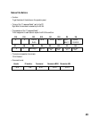
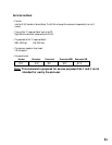
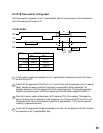
Note: If the RE-350 does not follow the above timing chart, the power or connection of the I/F cable is
incorrect.
RXD
CTS
TXD
1
2
3
4
6
5