


C-1
Cisco Aironet 1300 Series Outdoor Access Point/Bridge Hardware Installation Guide
OL-5048-02
APPENDIX
C
Access Point/Bridge Specifications
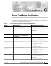
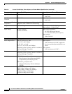
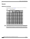
This appendix provides technical specifications for the access point/bridge, power injector, and power
module. Table C-1 lists the technical specifications.
Table C-1 Access Point/Bridge, Power Injector, and Power Module Specifications
Category Access Point/Bridge Power Injector and Power Module
Size Integrated antenna configuration:
8.00 in. W x 8.10 in. H 2.62 in. D
(20.32 cm W x 20.57 cm H 6.66 cm D)
Power injector:
4.62 in. W x 4.76 in. H x 1.07 in. D
(11.74 cm W x 12.09 cm H x 2.72 cm D)
Power module:
3.88 in. L x 1.24 in. W x 2.17 in. D
(98.5 mm L x 31.4 mm W x 55.0 mm D)
LEDs Four LEDs on the back panel: Radio traffic,
Ethernet traffic, status, and Installation and
Alignment Mode
One bi-color power LED on the side panel
Connectors Bottom panel (left to right): Power injector
dual-coax ports (two F-type connectors) and two
reverse-TNC antenna connectors
Side panel (left to right): Two coaxial uplink
F-type connectors, 48-VDC power connector,
RJ-45 connector for 100BASE-T Ethernet,
and a RJ-45 serial console port connector
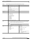
Operating Temperature –22 to 131
o
F (–30 to 55
o
C) Power injector:
–22 to 131
o
F (–30 to 55
o
C)
Power module:
32 to 104
o
F (0 to 40
o
C)
Non-Operational
Temperature
–40 to 185
o
F (–40 to 85
o
C) Power injector:
–40 to 185
o
F (–40 to 85
o
C))
Power module:
–40 to 185
o
F (–40 to 85
o
C)
(10,000 ft. limit)
Humidity 0 to 90% (condensing) Power injector:
0 to 90% (non-condensing)
Power module:
0 to 95% (non-condensing)