


7-2
Cisco Aironet 1300 Series Outdoor Access Point/Bridge Hardware Installation Guide
OL-5048-02
Chapter 7 Troubleshooting
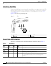
Checking the LEDs
Checking the LEDs
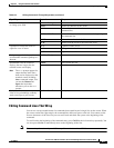
If your access point/bridge is not associating with a remote bridge or access point, check the four LEDs
on the back panel. You can use them to quickly assess the unit’s status. For information on using the
LEDs during the installation and alignment of the access point/bridge antenna, refer to the “LEDs”
section on page 3-5.
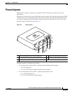
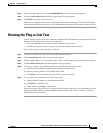
Figure 7-1 shows the access point/bridge LEDs.
Figure 7-1 LEDs
Normal Mode LED Indications
During access point/bridge operation the LEDs provide status information as shown in Table 7-1.
R Radio LED E Ethernet LED
S Status LED I Install LED
117061
RS
I
E
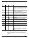
Table 7-1 LED Indications
Ethernet
LED
Status
LED
Radio
LED
Install
LED
Meaning
Off — — — Ethernet link is down or disabled.
Blinking
green
— — — Transmitting and receiving Ethernet packets.
Blinking
amber
— — — Transmitting and receiving Ethernet errors.
amber — — — Firmware error—disconnect and reconnect the power injector power
jack. If the problem continues, contact technical support for
assistance.