


5-4
Cisco Aironet 1300 Series Outdoor Access Point/Bridge Hardware Installation Guide
OL-5048-02
Chapter 5 Configuring the Access Point/Bridge for the First Time
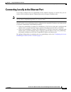
Connecting to the Access Point/Bridge Locally
Connecting to the Access Point/Bridge Locally
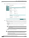
Using the Power Injector’s Ethernet Port
You can use the power injector’s Ethernet port to configure the access point/bridge locally (without
connecting to a wired LAN) using the web-browser or CLI interfaces. Follow these steps to connect to
the power injector’s Ethernet port:
Step 1 Connect a Category 5 Ethernet cable to your PC’s Ethernet connector and to the power injector’s
Ethernet port.
Note You do not need a special crossover cable to connect your PC to the power injector’s Ethernet
port; you can use either a straight-through cable or a crossover cable.
Step 2 Your PC and the access point/bridge must be configured with compatible IP addresses and subnet masks
to be able to communicate on the Ethernet interface. Perform one of these operations:
a. If the access point/bridge is running Cisco IOS Release 12.2(15)JA or earlier and is configured with
default values, you must manually assign your PC an IP address from 10.0.0.31 to 10.0.0.40.
b. If the access point/bridge is running Cisco IOS Release 12.3(2)JA2 or later and is configured with
default values, you must manually assign a temporary static IP address to the access point/bridge
and manally configure your PC with a compatible IP address and subnet mask. For additional
information, refer to the Obtaining and Assigning an IP Address, page 5-3.
Using the Power Injector’s Console Port
You can use the power injector’s console port for entering CLI commands. Follow these steps to connect
to the power injector’s console port:
Step 1 Connect a nine-pin, female DB-9 to RJ-45 serial cable to the RJ-45 serial console port on the power
injector and to the COM port on a computer.
Note The Cisco part number for the DB-9 to RJ-45 serial cable is AIR-CONCAB1200. Browse to
http://www.cisco.com/go/marketplace to order a serial cable.
Step 2 Set up a terminal emulator to communicate with the access point. Use the following settings for the
terminal emulator connection: 9600 baud, 8 data bits, no parity, 1 stop bit, and no flow control.
Note When your configuration changes are completed, you must remove the serial cable from the console
port.