


1-5
Cisco Aironet 1300 Series Outdoor Access Point/Bridge Hardware Installation Guide
OL-5048-02
Chapter 1 Overview
Key Features
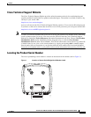
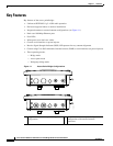
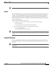
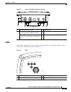
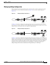
Figure 1-2 Access Point/Bridge Connector Locations
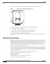
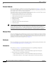
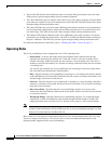
LEDs
Four LEDs are located on back of the housing to report installation and alignment conditions, status,
radio activity, and Ethernet activity (see Figure 1-3).
Figure 1-3 LEDs
1 Ground lug mounting screws 3 Mounting posts
2 Left antenna connector (external antenna
access point/bridge configuration only)
4 LEDs
Primary right antenna connector (external
antenna access point/bridge configuration
only)
5 Dual-coax Ethernet ports (F-Type connectors)
117060
1
2
3
4
5
R Radio LED (R) E Ethernet LED (E)
S Status LED (S) I Install LED (I)
117061
RS
I
E