


D-4
Cisco Aironet 1300 Series Outdoor Access Point/Bridge Hardware Installation Guide
OL-5048-02
Appendix D Channels and Antenna Settings
Maximum Power Levels and Antenna Gains
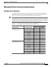
Changing the Access Point/Bridge Output Power
This section provides instructions for changing the access point/bridge output power to comply with the
maximum power limits imposed by regulatory domains (see “Maximum Power Levels and Antenna
Gains” section on page D-3). Follow these instructions to change the output power settings using your
browser:
Note Administrator privileges may be required in order to change access point/bridge settings.
Note To meet regulatory restrictions, the external antenna access point/bridge unit and the external antenna
must be professionally installed. The network administration or other IT professional responsible for
installing and configuring the unit is a suitable professional installer. Following installation, access to the
unit should be password protected by the network administrator to maintain regulatory compliance.
Step 1 Open your Internet browser.
Step 2 Enter the access point/bridge IP address in the browser address or location line and press Enter. An Enter
Network Password screen appears.
Step 3 Enter your username (default Cisco) in the User Name field.
Step 4 Enter the access point/bridge password (default Cisco) in the Password field and press Enter. The
Summary Status page appears.
Step 5 Click Network Interfaces and the network interface menu appears.
Step 6 Click Radio0-802.11G and the 802.11G Status screen appears.
Step 7 Click the Settings tab and the settings screen appears.
Step 8 On the CCK Transmit Power (mW) setting, select the maximum CCK power allowed for your antenna in
your regulatory region.
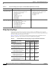
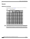
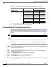
Japan (-J)
(10 mW/MHz EIRP maximum)
5.2 (Omni) 10 10
9 (Patch) 10 10
10 (Yagi) 10 10
11 (Omni) 10 10
12 (Omni) 10 10
13 (Integrated patch) 10 10
13.5 (Yagi) 10 10
14 (Sector) 10 10
21 (Dish) 10 10
1. A minimum of 2 dBi cable loss must be be used for this configuration.
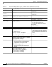
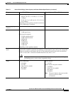
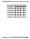
Table D-2 Maximum Power Levels Per Antenna Gain for IEEE 802.11g (continued)
Regulatory Domain Antenna Gain (dBi)
Maximum Power Level (mW)
CCK OFDM