


3-7
Cisco Aironet 1300 Series Outdoor Access Point/Bridge Hardware Installation Guide
OL-5048-02
Chapter 3 Mounting and Alignment Overview
Aligning the Bridge Antenna Using RSSI LED Indications
Aligning the Bridge Antenna Using RSSI LED Indications
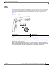
You can align the integrated antenna using LEDs after the unit successfully associates with a remote
bridge. In the installation mode before association to another bridge, the Install LED blinks amber. If the
unit associates to a root bridge, the Install LED turns amber. If the unit does not associate to a root bridge
in the first 60 seconds, the Install LED blinks green to indicate that beacons are being transmitted and
that the unit is waiting for another non-root bridge to associate.
During the first 20 seconds after association, the unit reads the receive signal strength indictor (RSSI)
levels and records the maximum level received. After 20 seconds have elapsed, the Install LED turns
amber and the Ethernet, status, and radio LEDs display the relative RSSI levels compared to the
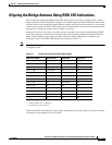
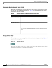
maximum received. The RSSI LED indications are shown in Table 3-3).
Note For the signal level (dBm), a smaller number represents a stronger signal because the signal level is given
as a negative value.
When using LEDs to maximize the signal, adjust the antenna until as many LEDs as possible are turned
on and the rest are blinking as fast as possible.
Table 3-3 Bridge LED Installation Mode RSSI Display
RSSI Level (dBm) Ethernet LED Status LED Radio LED
> –44 On On On
–47 to –44 Fast blink
1
1. Slow blinking rate of 1 blink/sec.
On On
–50 to –47 Medium blink
2
2. Medium blinking rate of 2 blinks/sec.
On On
–53 to –50 Slow blink
3
3. Fast blinking rate of 4 blinks/sec.
On On
–54 to –53 Off On On
–57 to –54 Off Fast blink
1
On
–60 to –57 Off Medium blink
2
On
–63 to –60 Off Slow blink
3
On
–66 to –63 Off Off On
–69 to –66 Off Off Fast blink
1
–72 to –69 Off Off Medium blink
2
–75 to –72 Off Off Slow blink
3
< –75 Off Off Off