


3-3
Cisco Aironet 1300 Series Outdoor Access Point/Bridge Hardware Installation Guide
OL-5048-02
Chapter 3 Mounting and Alignment Overview
Mounting Hardware
Window Mounting
When a wireless link is deployed through a window, significant signal loss can be introduced by the
window. Typical losses range from 5 to15 dB per window, depending upon the type of glass. You should
take this extra loss into account when planning antenna gains and power settings. A thorough site survey
is critical for deployments through windows.
For additional information on a window mounting bracket, refer to the following URL:
http://www.terrawave.com/BR1300
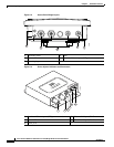
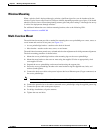
Multi-Function Mount
The multi-function mount provides a method for mounting the access point/bridge on a mast, tower, or
a roof mount and consists of two parts (see Figure 3-1):
• Access point/bridge bracket—attaches to the back of the unit
• Mast bracket—attaches to the mast, tower, or roof mount
The multi-function mount permits easy azimuth and elevation adjustments for bridge antenna alignment.
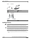
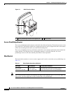
The basic mounting procedure is shown below:
1. Mount the access point/bridge bracket to the mounting lugs on the access point/bridge.
2. Mount the mast bracket to the tower or mast using the supplied U-bolts or appropriately sized
user-supplied U-bolts.
3. Suspend the access point/bridge on the mast bracket using the support pins.
4. Secure the access point/bridge bracket to the mast bracket using the supplied nuts, bolts, and
washers (hand tighten).
5. Connect the dual-coax cable to the power injector dual-coax Ethernet ports (F-type connectors) on
the access point/bridge.
Note You should securely tighten the cable connectors (15 to 20 inch-pounds) using a small wrench.
6. Connect the ground wire to the outdoor mounted access point/bridge using the supplied ground lug.
7. Connect the power cable to the power injector.
8. For bridge installations, align the antenna.
9. Tighten the nuts and bolts.