


E-2
Cisco Aironet 1300 Series Outdoor Access Point/Bridge Hardware Installation Guide
OL-5048-02
Appendix E Console Serial Cable Pinouts
Overview
Overview
The access point/bridge requires a special serial cable that connects the power injector’s console serial
port (RJ-45 connector) to your PC’s COM port (DB-9 connector). This cable can be purchased from
Cisco (part number AIR-CONCAB1200) or can be built using the pinouts in this appendix.
Signals and Pinouts
Use the RJ-45 to DB-9 serial cable to connect the power injector’s console serial port to the COM port
of your PC running a terminal emulation program.
Note Both the Ethernet and console serial ports use RJ-45 connectors. Be careful to avoid accidently
connecting the serial cable to the Ethernet port connector.
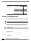
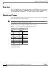
Table E-1 lists the signals and pinouts for the RJ-45 to DB-9 serial cable.
Table E-1 Signals and Pinouts for a RJ-45 to DB-9 Serial Cable
Serial Port PC COM Port
RJ-45 DB-9
Pins Signals
Pins Signals
1NC
1
1. NC indicates not connected.
––
2NC
1
––
3TXD
2
2. TXD indicates transmit data.
2RXD
4
4GND
3
3. GND indicates ground.
5GND
3
5GND
3
5GND
3
6RXD
4
4. RXD indicates receive data.
3TXD
2
7NC
1
––
8NC
1
––