


3-33
Cisco ONS 15454 SDH Reference Manual, R5.0
April 2008
Chapter 3 Electrical Cards
3.18 MIC-C/T/P FMEC
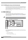
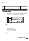
3.18 MIC-C/T/P FMEC
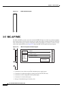
The MIC-C/T/P FMEC provides connection for the BATTERY A input, one of the two possible
redundant power supply inputs. It also provides connection for system management serial port, system
management LAN port, modem port (for future use), and system timing inputs and outputs. Install the
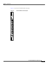
MIC-C/T/P in Slot 24. Figure 3-19 shows the MIC-C/T/P faceplate and block diagram.
Figure 3-19 MIC-C/T/P Faceplate and Block Diagram
The MIC-C/T/P FMEC has the following features:
• Connection for one of the two possible redundant power supply inputs
• Connection for two serial ports for local craft/modem (for future use)
• Connection for one LAN port
• Connection for two system timing inputs
• Connection for two system timing outputs
• Storage of manufacturing and inventory data
Note For proper system operation, both the MIC-A/P and the MIC-C/T/P FMECs must be installed in the
shelf.
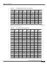
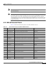
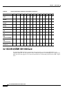
59 VISALM2 N Normally open Critical visual alarm Black/blue
60 VISALM2 P Normally open Critical visual alarm Blue/black
61 VISALM3 N Normally open Remote visual alarm Black/orange
62 VISALM3 P Normally open Remote visual alarm Orange/black
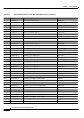
Table 3-16 Alarm Interface Pinouts on the MIC-A/P DB-62 Connector (continued)
Pin No. Signal Name Signal Description Color
Inventory Data
(EEPROM)
134376
B
a
c
k
p
l
a
n
e
3W3
connector
Power
RJ-45
connectors
System management serial ports
RJ-45
connectors
System management LAN
4 coaxial
connectors
Timing 2 x in / 2 x out
M
ACT
LINK
CLEI CODE BARCODE
+
AUTION
E FACEPLATE
1.0 Nm TORQUE