


10-8
Cisco ONS 15454 SDH Reference Manual, R5.0
April 2008
Chapter 10 Circuits and Tunnels
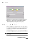
10.2.4 Circuit Information in the Edit Circuit Window
• The circuit source and destination points
• Open Shortest Path First (OSPF) area IDs
• Link protection (SNCP, unprotected, MS-SPRing, 1+1) and bandwidth (STM-N)
For MS-SPRings, the detailed map shows the number of MS-SPRing fibers and the MS-SPRing ring ID.
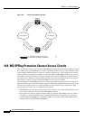
For SNCPs, the map shows the active and standby paths from circuit source to destination, and it also
shows the working and protect paths. The map indicates nodes set up as dual-ring interconnect nodes.
For VCAT circuits, the detailed map is not available for an entire VCAT circuit. However, you can view
the detailed map to view the circuit route for each individual member.
You can also view alarms and states on the circuit map, including:
• Alarm states of nodes on the circuit route
• Number of alarms on each node organized by severity
• Port service states on the circuit route
• Alarm state/color of the most severe alarm on the port
• Loopbacks
• Path trace states
• Path selectors states
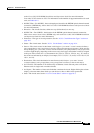
For example, in an SNCP, the working path is indicated by a green, bidirectional arrow, and the protect
path is indicated by a purple, bidirectional arrow. Source and destination ports are shown as circles with
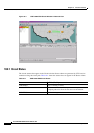
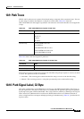
an S and a D. Port service states are indicated by colors, shown in Table 10-3.
A notation within or by the squares on each node indicates switches and loopbacks, including:
• F = Force switch
• M = Manual switch
• L = Lockout switch
• Arrow = Facility (outward) or terminal (inward) loopback
Figure 10-2 shows an example of an SNCP with a card in terminal loopback in the Edit Circuits window.
Table 10-3 Port State Color Indicators
Port Color Service State
Green Unlocked-enabled
Gray Locked-enabled,disabled
Violet Unlocked-disabled,automaticInService
Blue (Cyan) Locked-enabled,maintenance