


2-14
Cisco ONS 15454 SDH Reference Manual, R5.0
April 2008
Chapter 2 Common Control Cards
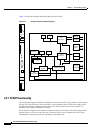
2.5.1 XC-VXL-10G Functionality
2.5.1 XC-VXL-10G Functionality
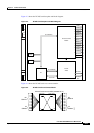
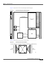
The XC-VXL-10G card manages up to 192 bidirectional STM-1 cross-connects, 192 bidirectional E-3
or DS-3 cross-connects, or 1008 bidirectional E-1 cross-connects. The TCC2/TCC2P card assigns
bandwidth to each slot on a per STM-1 basis. The XC-VXL-10G card works with the TCC2/TCC2P card
to maintain connections and set up cross-connects within the node. You can establish cross-connect and
provisioning information through CTC.
Note Cisco does not recommend operating the ONS 15454 SDH with only one XC-VXL-10G card. To
safeguard your node, always operate in a redundant configuration. Install the XC-VXL-10 cards in
Slots 8 and 10.
2.5.2 XC-VXL-10G Card-Level Indicators
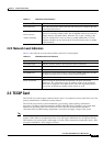
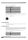
Table 2-12 describes the two card-level LEDs on the XC-VXL-10G card faceplate.
2.6 XC-VXL-2.5G Card
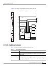
The XC-VXL-2.5G card cross-connects E-1, E-3, DS-3, STM-1, STM-4, STM-16, and STM-64 signal
rates. The XC-VXL-2.5G card provides a maximum of 192 x 192 VC-4 nonblocking cross-connections,
384 x 384 VC-3 nonblocking cross-connections, or 2016 x 2016 VC-12 nonblocking cross-connections.
The card is designed for 2.5-Gbps solutions.
Note The XC-VXL-2.5G card has been designed to support both –48 VDC and –60 VDC input requirements.
Table 2-12 XC-VXL-10G Card-Level Indicators
Card-Level LEDs Definition
Red FAIL LED Indicates that the card’s processor is not ready. The FAIL LED is on during
reset and flashes during the boot process. Replace the card if the red FAIL
LED persists.
ACT/STBY LED
Green (Active)
Amber (Standby)
Indicates whether the XC-VXL-10G card is active and carrying traffic
(green) or in standby mode to the active XC-VXL-10G card (amber).