


11-28
Cisco ONS 15454 SDH Reference Manual, R5.0
April 2008
Chapter 11 SDH Topologies and Upgrades
11.6 Linear ADM Configurations
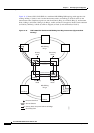
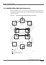
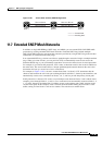
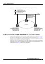
Figure 11-27 shows two MS-SPRings shared by one ONS 15454 SDH. Ring 1 runs on Nodes 1, 2, 3, and
4. Ring 2 runs on Nodes 4, 5, 6, and 7. Two MS-SPRing, Ring 1 and Ring 2, are provisioned on Node 4.
Ring 1 uses cards in Slots 5 and 12, and Ring 2 uses cards in Slots 6 and 13.
Note Nodes in different MS-SPRings can have the same or different node IDs.
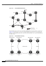
Figure 11-27 MS-SPRing Subtending from an MS-SPRing
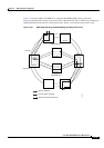
After subtending two MS-SPRings, you can route circuits from nodes in one ring to nodes in the second
ring. For example, in Figure 11-27 you can route a circuit from Node 1 to Node 7. The circuit would
normally travel from Node 1 to Node 4 to Node 7. If fiber breaks occur, for example between Nodes 1
and 4 and Nodes 4 and 7, traffic is rerouted around each ring: in this example, Nodes 2 and 3 in Ring 1
and Nodes 5 and 6 in Ring 2.
11.6 Linear ADM Configurations
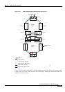
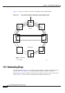
You can configure ONS 15454 SDHs as a line of add/drop multiplexers (ADMs) by configuring one set
of STM-N cards as the working path and a second set as the protect path. Unlike rings, linear
(point-to-point) ADMs require that the STM-N cards at each node be in 1+1 protection to ensure that a
break to the working line is automatically routed to the protect line.
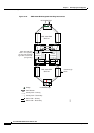
Figure 11-28 shows three ONS 15454 SDH nodes in a linear ADM configuration. Working traffic flows
from Node 1/Slot 5 to Node 2/Slot 5, and from Node 2/Slot 12 to Node 3/Slot 12. You create the protect
path by placing Slot 6 in 1+1 protection with Slot 5 at Nodes 1 and 2, and placing Slot 12 in
1+1 protection with Slot 13 at Nodes 2 and 3.
Node 5
Slot 6
West
East
Slot 13
Node 7
Slot 13
East
Slot 6
West
Slot 6
West
Slot 13
East
Node 6
Node 1
Slot 5
West
Slot 5
West
Slot 12
East
Slot 12
East
Node 3
Slot 12
East
Slot 5
West
Node 2
Slot 5
West
Slot 12
East
Slot 13
East
Slot 6
West
Node 4
MS-SPRing 1 MS-SPRing 2
71272