


REVIEW DRAFT—CISCO CONFIDENTIAL
14-11
Cisco ONS 15454 SDH Reference Manual, R5.0
April 2008
Chapter 14 Ethernet Operation
14.3.1 E-Series Modes
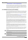
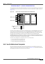
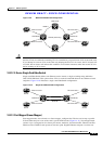
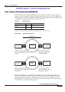
Figure 14-9 Multicard EtherSwitch Configuration
Caution Whenever you terminate two VC4-2c multicard EtherSwitch circuits on an Ethernet card and later delete
the first circuit, also delete the remaining VC4-2c circuit before you provision an VC4 circuit to the card.
If you attempt to create an VC4 circuit after only deleting the first VC4-2c circuit, the VC4 circuit will
not work, but no alarms will indicate this condition. To avoid this situation, delete the second VC4-2c
before creating an VC4 circuit.
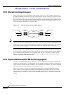
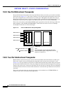
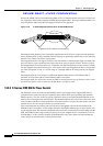
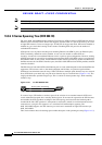
14.3.1.2 E-Series Single-Card EtherSwitch
Single-card EtherSwitch allows each Ethernet card to remain a single switching entity within the
ONS 15454 SDH shelf. This option allows VC4-4c worth of bandwidth between two Ethernet circuit
endpoints. Figure 14-10 illustrates a single-card EtherSwitch configuration.
Figure 14-10 Single-Card EtherSwitch Configuration
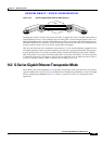
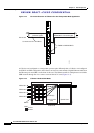
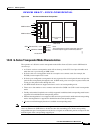
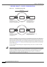
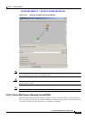
14.3.1.3 Port-Mapped (Linear Mapper)
Port-mapped mode, also referred to as linear mapper, configures the E-Series card to map a specific
E-Series Ethernet port to one of the card’s specific STM circuits (Figure 14-11). Port-mapped mode
ensures Layer 1 transport has low latency for unicast, multicast, and mixed traffic. Ethernet and Fast
Ethernet on the E100T-G card operate at line-rate speed. Gigabit Ethernet transport is not line rate
ONS NodeONS Node
ONS Node
ONS Node
Router
Ethernet card 3
Router
Router
Router
Ethernet card 1
Ethernet card 4
Ethernet card 2
Shared packet ring
VLAN A
45133
ONS NodeONS Node
Router
Ethernet card 3
Router
Router
Router
Ethernet card 1
Ethernet card 4
Ethernet card 2
VLAN B
VLAN A
45132