


4-14
Cisco ONS 15454 SDH Reference Manual, R5.0
April 2008
Chapter 4 Optical Cards
4.5.1 OC12 LR/STM4 LH 1310 Card-Level Indicators
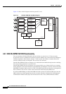
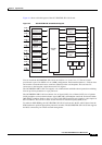
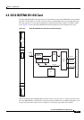
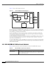
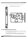
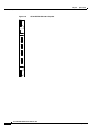
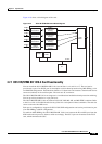
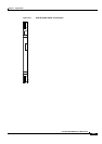
Figure 4-7 shows a block diagram of the card.
Figure 4-7 OC12 LR/STM4 LH 1310 Block Diagram
You can install the OC12 LR/STM4 LH 1310 card in Slots 1 to 6 and 12 to 17 and provision the card as
part of an MSP-SPRing or SNCP ring. In ADM configurations, you can provision the card as either an
access tributary or a transport span-side interface.
The OC12 LR/STM4 LH 1310 card interface features a 1310-nm laser and contains a transmit and
receive connector (labeled) on the card faceplate. The card uses SC optical connections and supports
1+1 unidirectional and bidirectional protection.
The OC12 LR/STM4 LH 1310 detects LOS, LOF, LOP, MS-AIS, and MS-FERF conditions. Refer to the
Cisco ONS 15454 SDH Troubleshooting Guide for a description of these conditions. The card also
counts section and line BIP errors.
To enable an MSP-SPRing, the OC12 LR/STM4 LH 1310 extracts the K1 and K2 bytes from the SDH
overhead to perform appropriate protection switches. The GCC bytes are forwarded to the TCC2 card,
which terminates the GCC.
4.5.1 OC12 LR/STM4 LH 1310 Card-Level Indicators
Table 4-6 describes the three card-level LED indicators on the OC12 LR/STM4 LH 1310 card.
uP bus
uP
Flash
RAM
STM-4
Mux/
Demux
Optical
Transceiver
STM-4
Main SCI
Protect SCI
Cross
Connect
Matrix
STM-4
B
a
c
k
p
l
a
n
e
61225
Table 4-6 OC12 LR/STM4 LH 1310 Card-Level Indicators
Card-Level LED Description
Red FAIL LED The red FAIL LED indicates that the card’s processor is not ready. The FAIL
LED is on during reset and flashes during the boot process. Replace the card
if the red FAIL LED persists.