


3-6
Cisco ONS 15454 SDH Reference Manual, R5.0
April 2008
Chapter 3 Electrical Cards
3.2.2 E1-N-14 Card-Level Indicators
Note The lowest level cross-connect with the XC10G card is STM-1. Lower level signals, such as E-1, DS-3,
or E-3, can be dropped. This might leave part of the bandwidth unused. The lowest level cross-connect
with the XC-VXL-10G card and with the XC-VXL-2.5G card is VC-12 (2.048 Mbps).
3.2.2 E1-N-14 Card-Level Indicators
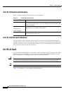
Table 3-3 describes the three E1-N-14 card faceplate LEDs.
3.2.3 E1-N-14 Port-Level Indicators
You can obtain the status of the 14 E-1 ports using the LCD screen on the ONS 15454 SDH fan-tray
assembly. Use the LCD to view the status of any port or card slot; the screen displays the number and
severity of alarms for a given port or slot. Refer to Cisco ONS 15454 SDH Troubleshooting Guide for a
complete description of the alarm messages.
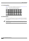
3.3 E1-42 Card
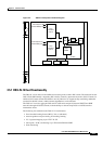
The 42-port ONS 15454 SDH E1-42 card provides 42 ITU-compliant, G.703 E-1 ports. Each port of the
E1-42 card operates at 2.048 Mbps over a 120-ohm, twisted-pair copper cable. Front mount electrical
connection is done using the FMEC E1-120 NP card for unprotected operation, the FMEC E1-120PROA
for 1:3 protection in the left side of the shelf, or the FMEC E1-120PROB for 1:3 protection in the right
side of the shelf.
Caution This interface can only be connected to SELV circuits. The interface is not intended for connection to
any Australian telecommunications network without the written consent of the network manager.
Note If you need 75-ohm unbalanced interfaces, you must additionally use the E1-75/120 conversion panel.
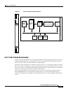
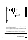
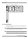
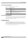
Figure 3-2 shows the E1-42 card faceplate and block diagram.
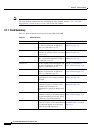
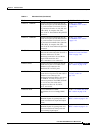
Table 3-3 E1-N-14 Card-Level Indicators
Card-Level LEDs Description
Red FAIL LED Indicates that the card’s processor is not ready. The FAIL LED is on during
reset and flashes during the boot process. Replace the card if the FAIL LED
persists in flashing.
ACT/STBY LED
Green (Active)
Amber (Standby)
Indicates that the E1-N-14 card is operational and ready to carry traffic
(green) or that the card is in Standby mode (amber).
Amber SF LED Indicates a signal failure or condition such as loss of signal (LOS), loss of
frame (LOF), or high BERs on one or more of the card’s ports.