


2-7
Cisco ONS 15454 SDH Reference Manual, R5.0
April 2008
Chapter 2 Common Control Cards
2.2.3 Network-Level Indicators
2.2.3 Network-Level Indicators
Table 2-8 describes the six network-level LEDs on the TCC2 card faceplate.
2.3 TCC2P Card
The TCC2P card, which requires Software R4.0 or later, is an enhanced version of the TCC2 card. The
primary enhancements are Ethernet security features.
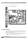
The TCC2P card performs system initialization, provisioning, alarm reporting, maintenance,
diagnostics, IP address detection/resolution, SONET SOH DCC/GCC termination, and system fault
detection for the ONS 15454. The TCC2P also ensures that the system maintains Stratum 3
(Telcordia GR-253-CORE) timing requirements. It monitors the supply voltage of the system.
Note The LAN interface of the TCC2P card meets the standard Ethernet specifications by supporting a cable
length of 328 ft (100 m) at temperatures from 32 to 149 degrees Fahrenheit (0 to 65 degrees Celsius).
The interfaces can operate with a cable length of 32.8 ft (10 m) maximum at temperatures from –40 to
32 degrees Fahrenheit (–40 to 0 degrees Celsius).
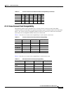
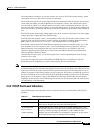
Table 2-7 TCC2 Card-Level Indicators
Card-Level LEDs Definition
Red FAIL LED The FAIL LED flashes during the boot and write process. Replace the card
if the FAIL LED persists.
ACT/STBY LED
Green (Active)
Amber (Standby)
The ACT/STBY (Active/Standby) LED indicates the TCC2 card is active
(green) or in standby (amber) mode. The ACT/STBY LED also provides the
timing reference and shelf control. When the TCC2 card is writing to the
active or standby TCC2 card, its active or standby LED blinks. To avoid
memory corruption, do not remove the TCC2 card when the active or standby
LED is blinking.
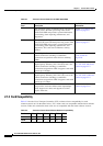
Table 2-8 TCC2 Network-Level Indicators
System-Level LEDs Definition
Red CRIT LED Indicates Critical alarms in the network at the local terminal.
Red MAJ LED Indicates Major alarms in the network at the local terminal.
Amber MIN LED Indicates Minor alarms in the network at the local terminal.
Red REM LED Provides first-level alarm isolation. The remote (REM) LED turns red when
an alarm is present in one or several of the remote terminals.
Green SYNC LED Indicates that node timing is synchronized to an external reference.
Green ACO LED After pressing the alarm cutoff (ACO) button, the green ACO LED
illuminates. The ACO button opens the audible closure on the backplane.
ACO state is stopped if a new alarm occurs. After the originating alarm is
cleared, the ACO LED and audible alarm control are reset.