


21
Installing and Upgrading Internal Modules in Cisco 2800 Series Routers
OL-5792-04
Installing and Removing AIMs
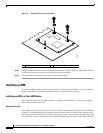
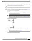
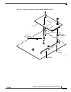
Step 3
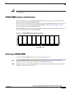
Install the two machine-thread metal standoffs into the system board in the metal standoff attachment
locations, as shown in
Figure 18. Use a 1/4-inch nut driver to tighten the standoffs. Locations for AIM
standoffs are denoted by a star pattern around the standoff mounting holes.
Caution
Make sure that the standoffs are straight when installed. Tighten them gently but firmly. The shoulder
must be seated tightly against the system board.
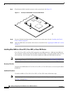
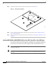
Step 4
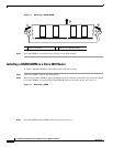
If you have a Cisco 2801 router, insert the plastic standoff with a snap fit on the ends (see Figure 20)
from the accessory kit into the hole in the system board. See Figure 18. Press the standoff firmly into the
system board to be sure that it is locked to the board.
Note
The Cisco 2801 router does not have a screw in the spot labeled B in Figure 22. Instead, there is
a hole in the system board in approximately the same location. Insert the plastic standoff in the
hole in the system board on Cisco 2801 routers.
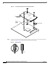
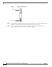
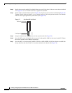
Note
The plastic standoff snaps into the system board. Be sure to insert the locking end of the standoff
into the system board. The locking end is the shortest end of the standoff.
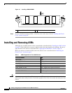
Figure 20 identifies
the locking end of the plastic standoff used with compression AIMs.
Figure 20 Plastic Standoff Orientation
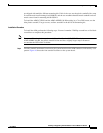
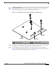
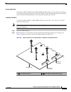
Step 5
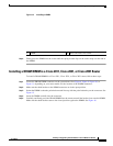
Insert the connector on the AIM into the AIM connector on the system board. See Figure 18.
Note
Be sure to press firmly on the AIM until the board seats onto the connector. The plastic standoff
must snap into the hole in the AIM board. See Figure 18.
Step 6
Insert the screws from the accessory kit through the AIM into the metal standoffs. See Figure 18.
Carefully tighten the screws with a Phillips screwdriver.
82620
AIM end
Locking end