


11
Overview of Cisco 2800 Series Routers
OL-5783-01
Chassis Views
Warning
There is the danger of explosion if the battery is replaced incorrectly. Replace the battery only with
the same or equivalent type recommended by the manufacturer. Dispose of used batteries according
to the manufacturer’s instructions.
Statement 1015
Chassis Views
This section contains views of the front and rear panels of the Cisco 2800 series routers, showing
locations of the power and signal interfaces, module slots, status indicators, and chassis identification
labels.
Cisco 2801 Chassis
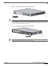
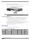
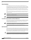
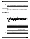
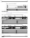
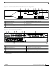
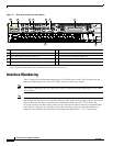
Figure 7 shows the front panel of a Cisco 2801 router. Figure 8 shows the back panel.
Figure 7 Front Panel of the Cisco 2801 Router
Double-wide HWICs can go into slots 0 and 1, and into slots 2 and 3.
Note
Slot 0 does not support PRI on T1/E1 VWICs, only channel-associated signaling (CAS) digital voice.
1 Slot 0 (VIC or VWIC, for voice only) 8 Auxiliary Power (AUX/PWR) LED
2 Slot 1 (WIC, VIC, VWIC, or HWIC) 9 Universal serial bus (USB) port
3 Slot 2 (WIC, VIC, or VWIC) 10 AIM/PVDM LEDs
4 Slot 3 (WIC, VIC, VWIC, or HWIC) 11 Auxiliary port
5 Console port 12 Compact flash (CF) LED
6 Fast Ethernet ports and LEDs 13 External CompactFlash memory card slot
7 System LEDs 14 Removable center card guides to allow
double-wide HWIC-D installation
95816
1234
5
6
7 9 11 12 13 14 14
8 10