


28
Installing and Upgrading Internal Modules in Cisco 2800 Series Routers
OL-5792-04
Installing and Removing AIMs
Step 3
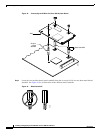
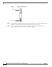
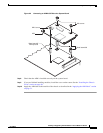
Install the two metal standoffs (included in the accessory kit) in place of the two screws that are labeled
A in
Figure 26. Use a 1/4-inch nut driver to tighten the standoffs.
Step 4
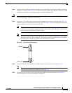
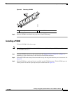
Install the hex standoff with the top band (Figure 27)) in place of the screw that is labeled B in Figure 26.
Tighten it firmly with your fingers, or very carefully using a 3/16-inch open-end wrench. The shoulder
must be seated tight against the system board. (See
Figure 28.)
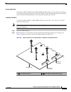
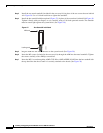
Figure 27 Hex Standoff with Band
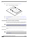
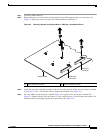
Step 5
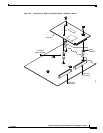
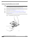
Plug the AIM into the AIM connector on the system board. (See Figure 28.)
Step 6
Insert the M3 screws (included in the accessory kit) through the AIM into the metal standoffs. Tighten
the screws carefully with a Phillips screwdriver.
Step 7
Insert the M2.5 screw through the AIM2-CUE-K9 or AIM2-APPRE-104-K9 into the hex standoff with
the top band into the chassis until it is securely attached to the board. (See
Figure 28.)
247136
AIM end
Locking end