


9
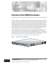
Overview of Cisco 2800 Series Routers
OL-5783-01
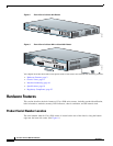
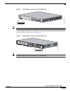
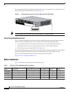
Hardware Features
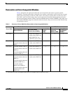
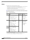
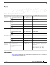
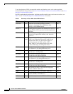
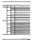
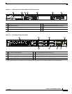
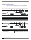
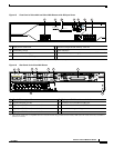
Ta b l e 6 Summary of Cisco 2811, Cisco 2821, and Cisco 2851 Series LED Indicators
LED Location LED Label
LED Color or
State
Meaning
Front of chassis SYS
PWR
Solid green System is operating normally
Blinking green System is booting or is in ROM monitor mode
Amber System error
Off Power is off or system board is faulty
AUX/
PWR
Green IP phone power operating normally (if installed), or
Cisco Redundant Power System (RPS) operating normally (if
installed)
Amber IP phone power fault (if installed), or
Cisco Redundant Power System (RPS) fault (if installed)
Off IP phone power and Cisco RPS are not installed
SYS
ACT
Blinking green
or solid green
Packet transfers are occurring
Off No packet transfers are occurring
CF Green Flash memory is being accessed; do not eject the CompactFlash
memory card
Off Flash memory is not being accessed; okay to eject the CompactFlash
memory card
Rear of chassis A (=ACT) Blinking green
or solid green
Packet activity in FE or GE port
Off No packet activity in FE or GE port
F (=FDX) Green FE or GE port is operating in full-duplex mode
Off FE or GE port is operating in half-duplex mode
S (= Speed)
1
1. The Ethernet S (Speed) LED blinks only when the L (Link) LED is on.
1 blink + pause FE or GE port operating at 10 Mbps
2 blinks + pause FE or GE port operating at 100 Mbps
3 blinks + pause GE port operating at 1000 Mbps (Cisco 2821 and Cisco 2851 only)
L (= Link) Green FE or GE link is established
Off No FE or GE link is established
PVDM0
PVDM1
PVDM2
2
2. The PVDM2 LED is applicable only to the Cisco 2821 and Cisco 2851 routers.
Green PVDM in slot (0, 1, or 2) is initialized
Amber PVDM in slot (0, 1, or 2) is detected but not initialized
Off No PVDM installed in slot (0, 1, or 2)
AIM0
AIM1
Green AIM in slot (0 or 1) is initialized
Amber AIM in slot (0 or 1) has initialization error
Off No AIM installed in slot (0 or 1)