


38
Installing and Upgrading Internal Modules in Cisco 2800 Series Routers
OL-5792-04
Replacing the Power Supply
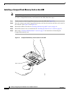
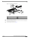
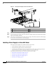
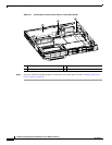
Figure 36 Inserting the ILP Supply into the Cisco 2801 Router
Step 6
Insert the screws that fasten the ILP supply to the chassis.
Step 7
Connect the main power supply cable to the main power supply connector, and connect the ILP supply
cable to the ILP supply connector.
Step 8
Verify that the vent blocking plate has been removed in Step 4. The ILP fans should be visible through
the vents that were blocked by the vent blocking plate.
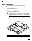
Installing a Power Supply in a Cisco 2811 Router
Three types of power supplies are available for the Cisco 2811 router:
•
An AC-input power supply, driven by external AC power
•
A DC-input power supply, driven by external DC power
•
An inline power (ILP) supply, driven by external AC power. This supply provides power for the
router and inline power for a complement of IP phones attached to the router.
The following sections describe how to install each type of power supply.
•
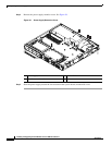
Removing the Existing Power Supply, page 39
•
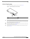
Installing an AC-Input Power Supply, page 41
•
Installing a DC-Input Power Supply, page 43
•
Installing an ILP Supply, page 45
1 ILP supply fastening screws 3 ILP connector
2 ILP supply 4 Main power connector
103060
1
4
3
2