


9-3
Catalyst 2940 Switch Software Configuration Guide
78-15507-02
Chapter 9 Configuring the Switch Interfaces
Understanding Interface Types
Port-Based VLANs
A VLAN is a switched network that is logically segmented by function, team, or application, without
regard to the physical location of the users. For more information about VLANs, see Chapter 13,
“Configuring VLANs.” Packets received on a port are forwarded only to ports that belong to the same
VLAN as the receiving port. Network devices in different VLANs cannot communicate with one another
without a Layer 3 device to route traffic between the VLANs.
VLAN partitions provide hard firewalls for traffic in the VLAN, and each VLAN has its own MAC
address table. A VLAN comes into existence when a local port is configured to be associated with the
VLAN, when the VLAN Trunking Protocol (VTP) learns of its existence from a neighbor on a trunk, or
when a user creates a VLAN.
To configure normal-range VLANs (VLAN IDs 1 to 1005), use the vlan vlan-id global configuration
command to enter config-vlan mode or the vlan database privileged EXEC command to enter VLAN
configuration mode. The VLAN configurations for VLAN IDs 1 to 1005 are saved in the VLAN
database.
Add ports to a VLAN by using the switchport interface configuration commands:
• Identify the interface.
• For a trunk port, set trunk characteristics, and if desired, define the VLANs to which it can belong.
• For an access port, set and define the VLAN to which it belongs.
EtherChannel Port Groups
EtherChannel port groups provide the ability to treat multiple switch ports as one switch port. These port
groups act as a single logical port for high-bandwidth connections between switches or between switches
and servers. An EtherChannel balances the traffic load across the links in the channel. If a link within
the EtherChannel fails, traffic previously carried over the failed link changes to the remaining links. You
can group multiple trunk ports into one logical trunk port or group multiple access ports into one logical
access port. Most protocols operate over either single ports or aggregated switch ports and do not
recognize the physical ports within the port group. Exceptions are the DTP, the Cisco Discovery Protocol
(CDP), the Port Aggregation Protocol (PAgP), and Link Aggregation Control Protocol (LACP) which
operate only on physical ports.
When you configure an EtherChannel, you create a port-channel logical interface and assign an interface
to the EtherChannel. For Layer 2 interfaces, the logical interface is dynamically created. You manually
assign an interface to the EtherChannel by using the channel-group interface configuration command.
This command binds the physical and logical ports together. For more information, see Chapter 25,
“Configuring EtherChannels.”
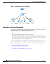
Connecting Interfaces
Devices within a single VLAN can communicate directly through any switch. Ports in different VLANs
cannot exchange data without going through a routing device or routed interface.
With a standard Layer 2 switch, ports in different VLANs have to exchange information through a router.
In the configuration shown in Figure 9-1, when Host A in VLAN 20 sends data to Host B in VLAN 30,
it must go from Host A to the switch, to the router, back to the switch, and then to Host B.