


14-5
Catalyst 2940 Switch Software Configuration Guide
78-15507-02
Chapter 14 Configuring VTP
Understanding VTP
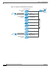
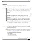
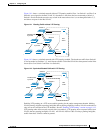
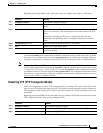
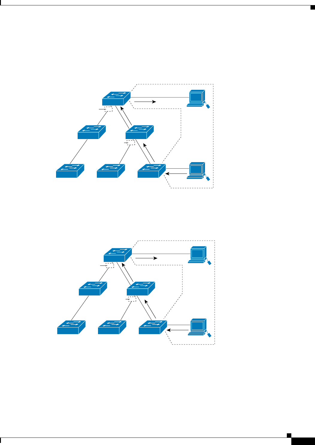
Figure 14-1 shows a switched network without VTP pruning enabled. Port 1 on Switch 1 and Port 2 on
Switch 4 are assigned to the Red VLAN. If a broadcast is sent from the host connected to Switch 1,
Switch 1 floods the broadcast and every switch in the network receives it, even though Switches 3, 5,
and 6 have no ports in the Red VLAN.
Figure 14-1 Flooding Traffic without VTP Pruning
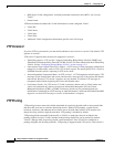
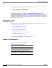
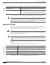
Figure 14-2 shows a switched network with VTP pruning enabled. The broadcast traffic from Switch 1
is not forwarded to Switches 3, 5, and 6 because traffic for the Red VLAN has been pruned on the links
shown (Port 5 on Switch 2 and Port 4 on Switch 4).
Figure 14-2 Optimized Flooded Traffic with VTP Pruning
Enabling VTP pruning on a VTP server enables pruning for the entire management domain. Making
VLANs pruning-eligible or pruning-ineligible affects pruning eligibility for those VLANs on that device
only (not on all switches in the VTP domain). See the “Enabling VTP Pruning” section on page 14-13.
VTP pruning takes effect several seconds after you enable it. VTP pruning does not prune traffic from
VLANs that are pruning-ineligible. VLAN 1 and VLANs 1002 to 1005 are always pruning-ineligible;
traffic from these VLANs cannot be pruned.
Switch 4
Switch 5
Switch 3Switch 6 Switch 1
Switch 2
Port 1
Port 2
Red
VLAN
87873
Port
4
Port
5
Flooded traffic
is pruned.
Flooded traffic
is pruned.
Switch 4
Switch 5
Switch 3Switch 6 Switch 1
Switch 2
Port 1
Port 2
Red
VLAN
87874
Port
4
Port
5
Flooded traffic
is pruned.
Flooded traffic
is pruned.