


4-8
Catalyst 2940 Switch Software Configuration Guide
78-15507-02
Chapter 4 Assigning the Switch IP Address and Default Gateway
Assigning Switch Information
Example Configuration
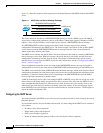
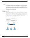
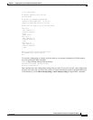
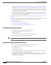
Figure 4-3 shows a sample network for retrieving IP information by using DHCP-based autoconfiguration.
Figure 4-3 DHCP-Based Autoconfiguration Network Example
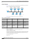
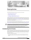
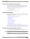
Table 4-2 shows the configuration of the reserved leases on the DHCP server.
DNS Server Configuration
The DNS server maps the TFTP server name maritsu to IP address 10.0.0.3.
TFTP Server Configuration (on UNIX)
The TFTP server base directory is set to /tftpserver/work/. This directory contains the network-confg file
used in the two-file read method. This file contains the host name to be assigned to the switch based on
its IP address. The base directory also contains a configuration file for each switch (switch1-confg,
switch2-confg, and so forth) as shown in this display:
prompt> cd /tftpserver/work/
prompt> ls
network-confg
switch1-confg
Switch 1
00e0.9f1e.2001
Cisco router
87795
Switch 2
00e0.9f1e.2002
Switch 3
00e0.9f1e.2003
DHCP server DNS server TFTP server
(maritsu)
10.0.0.1
10.0.0.10
10.0.0.2 10.0.0.3
Switch 4
00e0.9f1e.2004
Table 4-2 DHCP Server Configuration
Switch-1 Switch-2 Switch-3 Switch-4
Binding key
(hardware address)
00e0.9f1e.2001 00e0.9f1e.2002 00e0.9f1e.2003 00e0.9f1e.2004
IP address 10.0.0.21 10.0.0.22 10.0.0.23 10.0.0.24
Subnet mask 255.255.255.0 255.255.255.0 255.255.255.0 255.255.255.0
Router address 10.0.0.10 10.0.0.10 10.0.0.10 10.0.0.10
DNS server address 10.0.0.2 10.0.0.2 10.0.0.2 10.0.0.2
TFTP server name maritsu or 10.0.0.3 maritsu or 10.0.0.3 maritsu or 10.0.0.3 maritsu or 10.0.0.3
Boot filename
(configuration file)
(optional)
switch1-confg switch2-confg switch3-confg switch4-confg
Host name (optional) switch1 switch2 switch3 switch4