


5-20
Catalyst 2940 Switch Software Configuration Guide
78-15507-02
Chapter 5 Clustering Switches
Creating a Switch Cluster
• When the command switch is a Catalyst 2940 switches, all standby command switches must be
Catalyst 2940 switches.
• When the command switch is running Cisco IOS Release 12.0(5)WC2 or earlier, the standby
command switches can be these switches: Catalyst 2900 XL, Catalyst 2950, and Catalyst 3500 XL
switches.
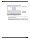
These abbreviations are appended to the switch host names in the Standby Command Group list to show
their eligibility or status in the cluster standby group:
• AC—Active command switch
• SC—Standby command switch
• PC—Member of the cluster standby group but not the standby command switch
• HC—Candidate switch that can be added to the cluster standby group
• CC—Command switch when HSRP is disabled
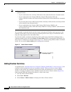
You must enter a virtual IP address for the cluster standby group. This address must be in the same subnet
as the IP addresses of the switch. The group number must be unique within the IP subnet. It can be
from 0 to 255, and the default is 0. The group name can have up to 31 characters.
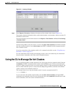
The Standby Command Configuration window uses the default values for the preempt and name
commands that you have set by using the CLI. If you use this window to create the HSRP group, all
switches in the group have the preempt command enabled. You must also provide a name for the group.
Note The HSRP standby hold time interval should be greater than or equal to 3 times the hello time interval.
The default HSRP standby hold time interval is 10 seconds. The default HSRP standby hello time
interval is 3 seconds. For more information about the standby hold time and hello time intervals, refer
to the Cisco IOS Release 12.1 documentation set on Cisco.com.
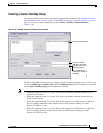
Verifying a Switch Cluster
When you finish adding cluster members, follow these steps to verify the cluster:
Step 1 Enter the command switch IP address in the browser Location field (Netscape Communicator) or
Address field (Microsoft Internet Explorer) to access all switches in the cluster.
Step 2 Enter the command-switch password.
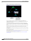
Step 3 Select View > Topology to display the cluster topology and to view link information. For complete
information about the Topology view, including descriptions of the icons, links, and colors, see the
“Topology View” section on page 3-14.