


1-3
Cisco Active Network Abstraction 3.6.6 MPLS User Guide
OL-19192-01
Chapter 1 Viewing MPLS VPNs
VPN Topology Connections
Layer 3 VPN Business Configuration
The following business elements represent a Layer 3 VPN configuration:
• Site (IP Interface)—Represents the VPN access point on the provider edge (PE) device.
• Virtual Router—Represents a PE VRF.
The Layer 3 VPN configuration hierarchy is composed of VPN business elements that in turn contain
multiple virtual routers and sites. The relationship between the contents of VPNs and virtual routers can
be changed, for example, by moving a virtual router between VPNs, which causes each site connected
to the moved virtual router to move as well. The relationship between virtual routers and sites cannot be
changed; sites are automatically attached to virtual routers (sites cannot be moved on their own).
In the Layer 3 VPN configuration, the VPNs are created and named automatically and new virtual routers
are automatically detected. The virtual router is then automatically related or matched to the VPN based
on the VRF name. If there is no related or matching VPN, then a new VPN is automatically created and
a VRF is assigned to it. You can then add these VPNs to a map. You can manually change the
autodiscovered service information, for example, by manually creating new VPNs, by deleting empty
VPNs, by renaming VPNs, and so on.
Cisco ANA can use different criteria to determine the different Layer 3 VPNs in the network and their
associated virtual routers. By default, Cisco ANA uses the VRF name to determine the network VPNs.
Layer 2 VPN Business Configuration and Tunnels
Layer 2 VPNs are not automatically created. You create the VPNs and then add the tunnels. The
following business elements represent the Layer 2 VPN configuration:
• Logical Circuit Peer (LCP)—Represents a Layer 2 tunnel edge that resides on a single device. A pair
of LCPs represents both sides of the tunnel edge.
Note A tunnel can be associated with only one VPN.
• Logical Circuit Aggregator (LCA)—Represents an aggregation of LCPs on the same device.
LCAs can be manually or automatically created:
–
Automatically—When an LCP is added to the VPN system, the system automatically creates
the LCA by taking all the LCPs that belong to the same device and aggregating them into an
LCA (the LCPs are automatically added under the LCA).
–
Manually—An LCA that is manually created on a specific VPN has no rules. Manually creating
an LCA is a preparatory step for adding tunnels or stranded peers.
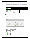
VPN Topology Connections
Cisco ANA uses route targets (based on the router configuration) to determine the topology between
VRFs. Layer 3 VPN topology information is continuously updated to reflect the actual state of the
network connections. Cisco ANA uses the virtual circuit (VC) ID and the router IP address (based on
the router configuration) to determine the connectivity between the Layer 2 tunnel edges forming the
pseudowire tunnels.