


6-2
Cisco Active Network Abstraction 3.6.6 MPLS User Guide
OL-19192-01
Chapter 6 IPv6 VPN over MPLS
6VPE Overview
6VPE Overview
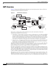
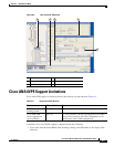
Figure 6-1 illustrates the 6VPE network architecture and control plane protocols when two IPv6 sites
communicate through an MPLS IPv4 backbone.
Figure 6-1 6VPE Network Architecture
Dual stack is a technique that lets IPv4 and IPv6 coexist on the same interfaces. Dual stack
implementations depend on the network area:
• Network Core—In the network core, IPv6 is carried in a VPN manner over a non IPv6-aware MPLS
core. This allows IPv4 or IPv6 communities to communicate with each other over an IPv4 MPLS
backbone without modifying the core infrastructure. By avoiding dual stacking on the core routers,
resources can be dedicated to their primary function to avoid any complexity on the operational side.
The transition and integration with respect to the current state of networks is also transparent.
• Network Access—To support native IPv6, the access that connects to IPv4 and IPv6 domains must
be IPv6-aware. Service PE elements can exchange routing information with end users; therefore,
dual stacking is a mandatory requirement on the access layer.
When IPv6 is enabled on the subinterface that is participating in a VPN, it becomes an IPv6 VPN. The
CE-PE link runs IPv6 or IPv4 natively. The addition of IPv6 on a PE router turns the PE into 6VPE,
thereby enabling service providers to support an IPv6 over the MPLS network.
PE routers use VRF tables to maintain the segregated reachability and forwarding information of each
IPv6 VPN. MP-BGP with its IPv6 extensions distributes the routes from 6VPE to other 6VPEs through
a direct interior BGP (iBGP) session or through VPNv6 route reflectors. The next hop of the advertising
PE router still retains the IPv4 address (normally it is a loopback interface), but with the addition of IPv6,
a value of ::FFFF: is prepended to the IPv4 next hop.
The technique can be seen as automatic tunneling of the IPv6 packets through the IPv4 backbone. The
MP-BGP relationships remain the same as they are for VPNv4 traffic, with an additional capability of
VPNv6. Where both IPv4 and IPv6 are supported, the same set of MP-BGP peering relationships is used.
PE1
2
200.11.11.1
PE2
4
5
200.10.10.1
routing table “blue”
routing table “red”
BGP table
Default
routing table
Provider
network
MP-iBGP
3
1
2001:100:2:1000::/562001:100:2:1000::/56
2001:100:1:1000::/56
200.14.14.1
2001:100:1:1000::/56
2001:100:2:1000::/64
2001:100:1:1000::/64
200.14.14.1
Customer#1
site1
Customer#2
site1
CE2CE2
CE1CE1
2001:100:1:2000::/64
2001:100:1:2000::/64
Customer#1
site2
Customer#2
site2
CE
CE
2001:100:1:2000::/562001:100:1:2000::/56
2001:100:2:2000::/562001:100:2:2000::/56
Default
routing table
210612