


1-4
Cisco Active Network Abstraction 3.6.6 MPLS User Guide
OL-19192-01
Chapter 1 Viewing MPLS VPNs
VPN Topology Connections
Cisco ANA shows the actual tunnel state (up or down) for the Layer 2 logical link if discovered. The link
appears with a minor severity (yellow) when the tunnel is down. Table 1-1 shows common MPLS VPN
topology map icons.
Note PE and customer edge (CE) Border Gateway Protocol (BGP) topologies are not supported.
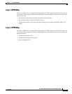
Figure 1-1 displays several devices that are connected in a multipath VPN MPLS map in the Cisco ANA
PathTracer multipath window.
Figure 1-1 Cisco ANA PathTracer Multipath Window
Table 1-2 lists the associations that might appear on the service view map.
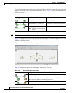
Table 1-1 Topology
Topology Example Line Description
Solid with arrows at either end. VPN topology (extranet).
Solid with arrows at either end. VPN topology between virtual routers.
Solid.
Note The link does not reflect a
status.
Tunnel topology between LCPs.
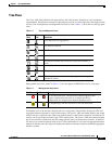
Table 1-2 Service View Map Associations
Association Example Description
The association between the customer site (IP interface) and the access
point on the PE.
The overall connection between the CE device and the site (IP interface),
which may cross different technologies and layers.
The overall connection between the CE device and the LCP.