


8-3
Cisco Active Network Abstraction 3.6.6 MPLS User Guide
OL-19192-01
Chapter 8 Impact Analysis in MPLS Networks
Supported Fault Scenarios
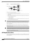
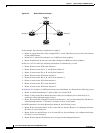
Figure 8-1 shows an example with two PEs, A and B, and a VRF in the same VPN. The Layer 3 VPN
faults that are reported are AX – BX.
Figure 8-1 Layer 3 VPN Example
Pseudowire (L2 VPN) Report
When a pseudowire tunnel goes down and an alarm occurs, the affected service resources are calculated
by tracing the LSP to the edge of the pseudowire tunnel and collecting the affected pairs from both sides
of the pseudowire tunnel. The edges of the tunnel are marked as affected.
The affected pairs are displayed in the Ticket Properties window. For more information about the Ticket
Properties window, see the Cisco Active Network Abstraction 3.6.6 User Guide.
Supported Fault Scenarios
The following fault scenarios trigger automatic impact analysis calculation:
• Link Down Scenario, page 8-4
• Link Overutilized/Data Loss Scenario, page 8-4
• BGP Neighbor Loss Scenario, page 8-5
• Broken LSP Discovered Scenario, page 8-7
• MPLS TE Tunnel Down Scenario, page 8-7
• Pseudowire MPLS Tunnel Down Scenario, page 8-7
The following criteria are used in the tables that are described in the sections that follow:
• Impact Calculation—Describes the way in which the affected parties are calculated by system flows.
• Reported Affected Severity—Describes the kind of severity generated by the alarm.
Note Proactive impact analysis is performed only for links.