


2-6
Cisco UCS C24 Server Installation and Service Guide
OL-26647-01
Chapter 2 Installing the Server
Installing the Server In a Rack
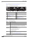
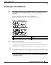
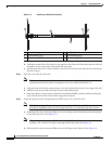
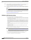
Figure 2-3 Attaching a Slide-Rail Assembly
d. Attach the second slide-rail assembly to the opposite side of the rack. Ensure that the two slide-rail
assemblies are level and at the same height with each other.
e. Pull the inner slide rails on each assembly out toward the rack front until they hit the internal stops
and lock in place.
Step 3 Insert the server into the slide rails:
Note The inner rails are pre-attached to the sides of the server at the factory. You can order
replacement inner rails if these are damaged or lost (Cisco PID UCSC-RAIL1-I).
a. Align the inner rails that are attached to the server sides with the front ends of the empty slide rails.
b. Push the server into the slide rails until it stops at the internal stops.
c. Push in the plastic release clip on each inner rail (labelled PUSH), and then continue pushing the
server into the rack until its front latches engage the rack posts.
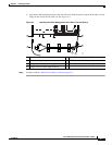
Step 4 Attach the (optional) cable management arm (CMA) to the rear of the slide rails:
Note The CMA is designed for mounting on either the right or left slide rails. These instructions
describe an installation to the rear of the right slide rails, as viewed from the rear of server.
a. Slide the plastic clip on the inner CMA arm over the flange on the mounting bracket that attached
to the side of the server. See
Figure 2-4.
Note Whether you are mounting the CMA to the left or right slide rails, be sure to orient the engraved
marking, “UP” so that it is always on the upper side of the CMA. See Figure 2-4.
b. Slide the plastic clip on the outer CMA arm over the flange on the slide rail. See Figure 2-4.
1 Front-left rack post 4 Length-adjustment bracket
2 Front mounting pegs 5 Rear mounting pegs
3 Slide-rail assembly 6 Rear securing latch
331689
1
3
2
5
6
4