


Contents
2
Cisco UCS C24 Server Installation and Service Guide
OL-26647-01
Cisco Integrated Management Interface (CIMC) 3-1
Server Configuration Utility 3-1
Status LEDs and Buttons 3-2
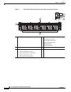
Front Panel LEDs 3-2
Rear Panel LEDs and Buttons 3-4
Preparing for Server Component Installation 3-6
Required Equipment 3-6
Shutting Down and Powering Off the Server 3-6
Removing and Replacing the Server Top Cover 3-7
Removing and Replacing the Front Chassis Panel 3-8
Replaceable Component Locations 3-9
Serial Number Location 3-9
Color-Coded Touch Points 3-10
Installing or Replacing Server Components 3-11
Replacing Hard Drives or Solid State Drives 3-12
Drive Population Guidelines 3-12
Drive Replacement Procedure 3-13
Replacing a Drive Backplane 3-14
Replacing a SAS Expander 3-16
Replacing Fan Modules 3-18
Replacing DIMMs 3-20
Memory Performance Guidelines and Population Rules 3-20
DIMM Replacement Procedure 3-23
Replacing CPUs and Heatsinks 3-24
Single-CPU Restrictions 3-24
CPU Replacement Procedure 3-24
Replacing the Motherboard RTC Battery 3-30
Replacing a PCIe Riser 3-32
Replacing a PCIe Card 3-34
PCIe Slots 3-34
Replacing a PCIe Card 3-35
Special Considerations for Cisco UCS Virtual Interface Cards 3-36
RAID Controller Card Cable Routing 3-36
Installing Multiple PCIe Cards and Resolving Limited Resources 3-37
Replacing a SuperCap Power Module (RAID Backup Unit) 3-39
Replacing a Cisco USB Flash Drive 3-41
Overview of the Pre-Loaded 16-GB Cisco USB Flash Drive 3-41
Enabling a Pre-Loaded Cisco USB Flash Drive Virtual Drive 3-41
Booting a Pre-Loaded Cisco USB Flash Drive Virtual Drive 3-42