


3-9
Cisco UCS C24 Server Installation and Service Guide
OL-26647-01z
Chapter 3 Maintaining the Server
Preparing for Server Component Installation
Replaceable Component Locations
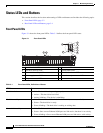
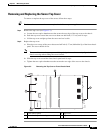
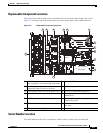
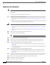
This section shows the locations of the components that are discussed in this chapter. The view in
Figure 3-4 is from the top down with the top cover, front chassis panel, and air baffle removed.
Figure 3-4 Replaceable Component Locations
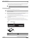
Serial Number Location
The serial number for the server is printed on a label on the top of the server, near the front.
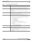
1 Drives
(hot-swappable, accessed through front panel)
8 Internal USB 2.0 port on motherboard
2 Drive backplane
(optionally either 24-drive or 16-drive)
9 RTC battery on motherboard
3 SAS expander (with 24-drive backplane only) 10 PCIe riser 2 (three half-height slots)
4 Fan modules (four) 11 Trusted platform module socket on
motherboard
5 DIMM slots on motherboard (twelve) 12 Power supplies (two, hot-swappable access
through rear panel)
6 CPUs and heatsinks (up to two) 13 RAID backup unit mounting cage (holds up to
two units)
7 PCIe riser 1 (two full-height slots)
285245
Port 1
Port 0
SYS FAN1
SYS FAN2
SYS FAN3
SYS FAN4
CPU 1
CPU 2
PCIe riser 1
PCIe riser 2
PSU 1 (bottom)
PSU 2 (top)
1
2 3 5 74 6
8
12
10
9
11
13