


3-33
Cisco UCS C24 Server Installation and Service Guide
OL-26647-01z
Chapter 3 Maintaining the Server
Installing or Replacing Server Components
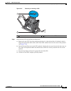
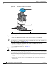
Caution Make sure that the circuit board connector of the riser is aligned correctly with the motherboard socket
before you push down to seat the riser in the next step.
c. Carefully push down on both ends of the PCIe riser to fully engage its circuit board connector with
the socket on the motherboard.
d. Reconnect cables to any PCIe cards installed in the riser.
e. Replace the top cover.
f. Replace the server in the rack, replace cables, and then power on the server by pressing the Power
button.
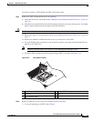
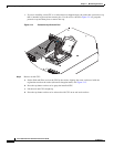
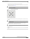
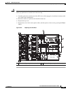
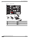
Figure 3-20 Replacing the PCIe Riser
1 PCIe riser 1 alignment point locations (three) 2 PCIe riser 2 alignment point locations (two)
285256
Port 1
Port 0
SYS FAN1
SYS FAN2
SYS FAN3
SYS FAN4
CPU 1
CPU 2
PCIe riser 1
PCIe riser 2
PSU 1 (bottom)
PSU 2 (top)
1
2
1