


3-16
Cisco UCS C24 Server Installation and Service Guide
OL-26647-01
Chapter 3 Maintaining the Server
Installing or Replacing Server Components
Replacing a SAS Expander
The SAS expander is a card that plugs directly into the drive backplane. The SAS expander allows
control of up to 24 drives with one RAID controller card. See
Appendix C, “RAID Controller
Considerations” for more information about supported RAID controllers.
Note The SAS expander is required for the SFF 24-drive option and the LFF 12-drive option.
The SFF 16-drive option does not use the SAS expander.
To install or replace a SAS expander, follow these steps:
Step 1 Prepare the server for component replacement:
a. Power off the server as described in the “Shutting Down and Powering Off the Server” section on
page 3-6.
b. Slide the server out the front of the rack far enough so that you can remove the top cover. You might
have to detach cables from the rear panel to provide clearance.
Caution If you cannot safely view and access the component, remove the server from the rack.
c. Remove the top cover as described in “Removing and Replacing the Server Top Cover” section on
page 3-7.
d. Remove the front chassis panel as described in Removing and Replacing the Front Chassis Panel,
page 3-8.
Step 2 Disconnect all cables from the SAS expander.
Tip Label the cables as you remove them to aid replacement.
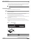
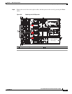
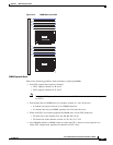
Step 3 Remove the SAS expander:
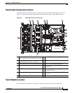
a. Remove the three screws that secure the SAS expander to the backplane assembly steel tray (see
Figure 3-9).
b. Grasp both ends of the SAS expander and pull evenly to disengage it from the sockets on the drive
backplane. Do not tilt the SAS expander until it is free from the sockets on the backplane.
Step 4 Install the new SAS expander:
a. Lower the SAS expander to its position on the backplane assembly. Return the SAS expander to a
horizontal position before you begin pushing it into the backplane sockets.
a. Evenly push the two connectors on the edge of the new SAS expander into the two sockets on the
backplane. Stop when the screw-holes in the SAS expander align with the screw-holes in the
backplane assembly steel tray.
b. Install the three screws that secure the SAS expander to the backplane assembly steel tray (see
Figure 3-9).
Step 5 Reconnect SAS cables to the new SAS expander.
Step 6 Replace the front chassis panel.
Step 7 Replace the top cover.