


3-2
Cisco UCS C24 Server Installation and Service Guide
OL-26647-01
Chapter 3 Maintaining the Server
Status LEDs and Buttons
Status LEDs and Buttons
This section describes the location and meaning of LEDs and buttons and includes the following topics
• Front Panel LEDs, page 3-2
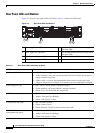
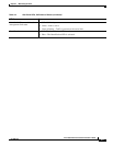
• Rear Panel LEDs and Buttons, page 3-4
Front Panel LEDs
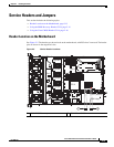
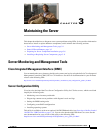
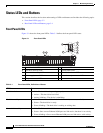
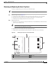
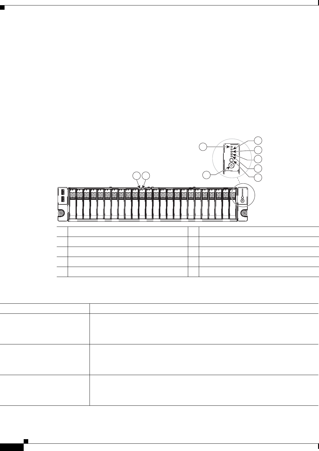
Figure 3-1 shows the front panel LEDs. Table 3-1 defines the front panel LED states.
Figure 3-1 Front Panel LEDs
1 Hard drive fault LED 6 Fan status LED
2 Hard drive activity LED 7 System status LED
3 Network link activity LED 8 Identification button/LED
4 Power supply status LED 9 Power button/power status LED
5 Temperature status LED –
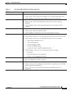
Ta b l e 3-1 Front Panel LEDs, Definitions of States
LED Name State
Hard drive fault • Off—The hard drive is operating properly.
• Amber—This hard drive has failed.
• Amber, blinking—The device is rebuilding.
Hard drive activity • Off—There is no hard drive in the hard drive sled (no access, no fault).
• Green—The hard drive is ready.
• Green, blinking—The hard drive is reading or writing data.
Network link activity • Off—The Ethernet link is idle.
• Green—One or more Ethernet LOM ports are link-active, but there is no activity.
• Green, blinking—One or more Ethernet LOM ports are link-active, with activity.
285243
HDD 01
HDD 02
HDD 03
HDD 04
HDD 05
HDD 06
HDD 07
HDD 08
HDD 09
HDD 10
HDD 11
HDD 12
HDD 13
HDD 14
HDD 15
HDD 16
HDD 17
HDD 18
HDD 19
HDD 20
HDD 21
HDD 22
HDD 23
HDD 24
1 2
3
4
5
7
8
9
6