


3-18
Cisco UCS C24 Server Installation and Service Guide
OL-26647-01
Chapter 3 Maintaining the Server
Installing or Replacing Server Components
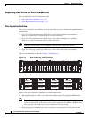
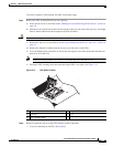
Replacing Fan Modules
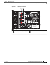
The four hot-pluggable fan modules in the server are numbered as follows when you are facing the front
of the server.
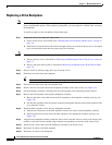
Figure 3-10 Fan Module Numbering
To replace or install a hot-pluggable fan module, follow these steps:
Caution You do not have to shut down or power off the server to replace fan modules because they are hot-
pluggable. However, to maintain proper cooling, do not operate the server for more than one minute with
any fan module removed.
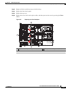
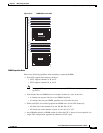
Step 1 Remove a fan module that you are replacing (see Figure 3-11):
a. Slide the server out the front of the rack far enough so that you can remove the top cover. You might
have to detach cables from the rear panel to provide clearance.
Caution If you cannot safely view and access the component, remove the server from the rack.
b. Remove the top cover as described in “Removing and Replacing the Server Top Cover” section on
page 3-7.
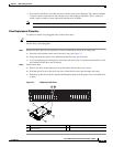
c. Grasp and squeeze together the two green plastic finger-latches on the top of the fan module and
then lift straight up to disengage the fan from the fan tray connector.
Step 2 Install a new fan module:
a. Set the new fan module in place, aligning the connector on the fan module with the connector on the
fan tray (see
Figure 3-11).
Note The arrow on the top of the fan module should point toward the rear of server.
b. Press down gently on the fan module until the finger-latches click and lock in place.
c. Replace the top cover.
d. Replace the server in the rack.
FAN1 FAN2 FAN3 FAN4