


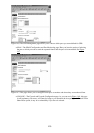
and want to retype an entry, click on Cancel to undo your first entry.
Note Again, keep in mind that if you are using IE5, you must use the Refresh button in your browser after
each configuration change to see the updates. Otherwise, you risk making a mistake down the line.
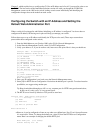
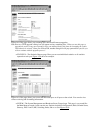
The CVSM default home page also has a real−time display of your switch. As we mentioned earlier, each port
has a colored LED display associated with it. Let’s look at what these LEDs represent, because they correlate
with the port’s configuration.
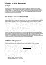
The Switch Image
Each port on the switch image has an LED above it. The following LEDs, as a group or individually, display
information about the switch and its individual ports:
Port Status (STAT)—The default view of the switch image. It focuses on the actual status of the
individual ports.
•
Bandwidth Utilization (UTL)—The percentage of the switch’s total bandwidth that is being used at
any given time.
•
Full−Duplex Operation (FDUP)—Which ports are operating in half− or full−duplex mode.•
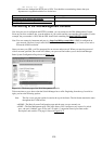
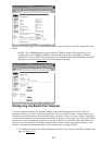
When you click on the Mode button on the switch image’s home page, you will change the currently selected
mode and the port LEDs. The LEDs change because they are related and work in conjunction with the mode
that is selected. By default, when STAT is selected, it shows the current port status; using UTL displays the
overall switch utilization; and FDUP displays which ports are configured and/or connected at full duplex. The
LED is green for whatever mode has been selected and once the selected mode has been active for about 30
seconds, the switch will return to its default mode, illuminating the STAT LED. You can change the default
mode by using the Console Settings menu on the management console.
On the top left side of the switch you will find another LED—System. The System LED’s colors indicates the
following:
Solid amber—The switch is receiving power but is not functioning properly. One or more power on
self tests (POSTs) have failed. The management console logon screen displays the failure.
•
Solid green—The switch is operating as designed.•
The Redundant Power Supply (RPS) LED’s color means the following:
Solid green—RPS is operational.•
Blinking green—AC power is on and RPS is up.•
Black (off)—RPS is off.•
Solid amber—RPS is connected but not working properly. A power supply in the RPS may have
powered down, or the fan on the RPS is out.
•
The STAT LED’s color indicates the following:
Solid amber—The specified port is not forwarding packets. The port could be administratively
disabled, disabled because of an address violation, or suspended by the Spanning−Tree Protocol
(STP) because of network−related loops.
•
Alternating green and amber—A problem exists, which may be due to any of the following: a link
fault, error frames (which can cause connectivity issues), collisions, or cyclic redundancy checks
(CRCs).
•
Black—No link exists.•
Solid green—The link is operational.•
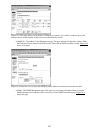
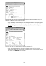
In the Immediate Solutions section we’ll walk through configuring the IP address and the Web CVSM
configuration settings on the Standard Edition IOS. If you are using the command line interface, refer to
274