


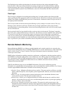
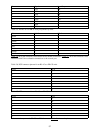
Pin Signal Input/Output
1 RTS Out
2 DTR Out
3 TXD Out
4 GND N/A
5 GND N/A
6 RXD In
7 DSR In
8 CTS In
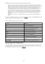
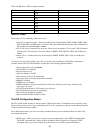
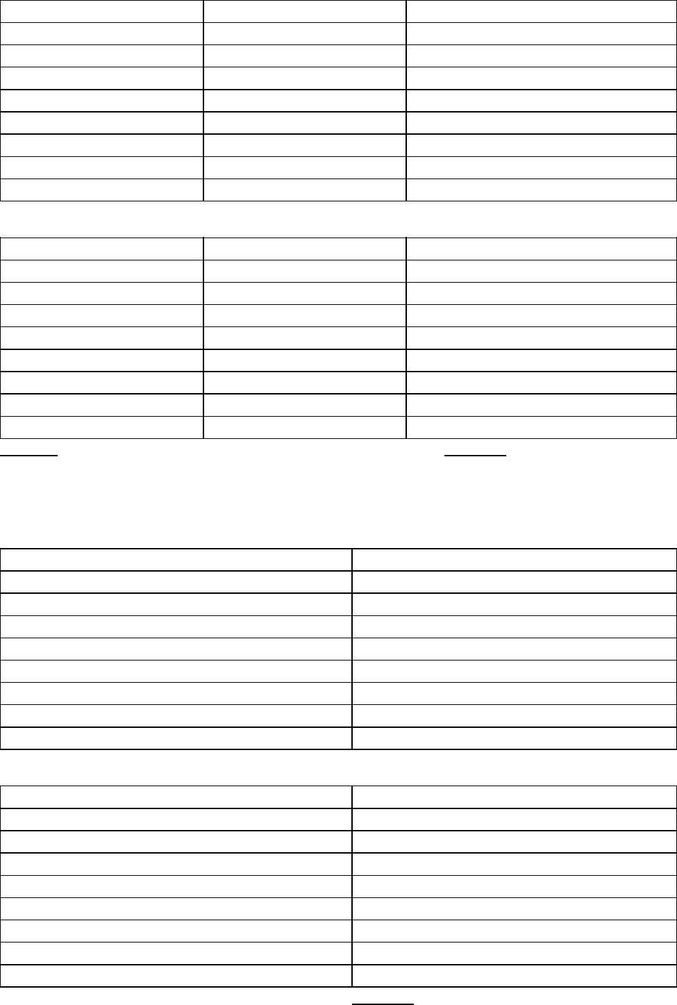
Table 2.5: The RJ−45−to−DB−9 AUX port pinouts by color.
Color RJ−45 DB−9
Brown 1 6
Blue 2 7
Yellow 3 2
Green 4 5
Red 5 5
Black 6 3
Orange 7 4
White 8 8
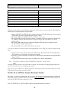
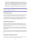
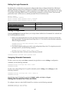
Table 2.6 shows the connectors most often used for modem connections. Table 2.7 shows the connectors most
often used with Unix workstation connections to the console port.
Table 2.6: DCE connector pinouts for an RJ−45 to a DB−25 male.
RJ−45 DCE
1 5
2 8
3 3
4 7
5 7
6 2
7 20
8 4
Table 2.7: DTE connectors for an RJ−45 to a DB−25 female.
RJ−45 DTE
1 4
2 20
3 2
4 7
5 7
6 3
7 6
8 5
In the event that you need a DB−25−to−DB−9 connector, Table 2.8 shows the pinouts.
37