


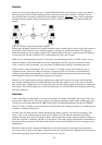


Poorly designed and implemented switched networks can have awful effects. Let’s take a look at the effects of
a flat area topology and how we can design, modify, and upgrade Ethernet networks to perform as efficiently
as possible.
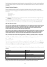
Properly Switched Networks
Properly switched networks use the Cisco hierarchical switching model to place switches in the proper
location in the network and apply the most efficient functions to each. In the model you will find switches in
three layers:
Access layer•
Distribution layer•
Core layer•
Note Chapter 2 will introduce the layers at which each switch can be found and the basic configuration steps
for both of the command line interfaces.
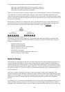
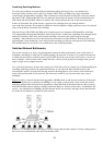
The Access layer’s primary function is to connect to the end−user’s interface. It routes traffic between ports
and broadcasts collision domain traffic to its membership broadcast domain. It is the access point into the
network for the end users. It can utilize lower−end switches such as the Catalyst 1900, 2800, 2900, 3500,
4000, and 5000 series switches.
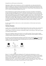
The Access layer switch blocks meet at the Distribution layer. It uses medium−end switches with a little more
processing power and stronger ASICs. The function of this layer is to apply filters, queuing, security, and
routing in some networks. It is the main processor of frames and packets flowing through the network.
Switches found at this layer belong to the 5500, 6000, and 6500 series.
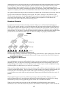
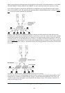
The Core layer’s only function is to route data between segments and switch blocks as quickly as possible. No
filtering or queuing functions should be applied at this layer. The highest−end Cisco Catalyst switches are
typically found at this layer, such as the 5500, 6500, 8500, 8600 GSR, and 12000 GSR series switches.
How you configure your broadcast and collision domains—whether in a switched network or a flat network
topology—can have quite an impact on the efficiency of your network. Let’s take a look at how utilization is
measured and the different effects bandwidth can have on different media types and networks.
Network Utilization
Network administrators vary on the utilization percentage values for normal usage of the network. Table 1.1
shows the average utilization that should be seen on the physical wire. Going above these averages of network
utilization on the physical wire is a sign that a problem exists in the network, that you need to make changes
to the network configuration, or that you need to upgrade the network.
Table 1.1: The average limits in terms of physical wire utilization. Exceeding these values indicates a network
problem.
Utilization (%) Medium Type
100 Full duplex
90 to 100 FDDI
90 to 100 Switched LAN segments
60 to 65 WAN links
35 to 45 Non−switched Ethernet segments or subnets
5 to 7 Collisions
You can use a network monitor such as a sniffer to monitor your utilization and the type of traffic flowing
through your network. Devices such as WAN probes let you monitor the traffic on the WAN.
18