


The BPX 8620 is a pure ATM broadband switch. It has a nonblocking 9.6Gbps architecture. The interface
modules range from T3 to OC−12. Each trunk port can buffer up to 32,000 cells. The OC−12 interface
module has two OC−12 ports. The OC−3 interface module has eight OC−3 ports. The BPX is commonly used
in conjunction with multiple MGX switches. The MGX concentrator terminates narrowband traffic to an
OC−3 trunk to the BPX 8620, which aggregates it to multiple OC−12s to the WAN ATM network.
With the popularity and the increase of TCP/IP traffic on the WAN, Cisco introduced the BPX 8650 to
enhance the functionality of the BPX series. The BPX 8650 adds a Label Switch Controller (LSC) to the BPX
8620. The LSC provides Layer 3 functionality to the ATM traffic. It enables the use of Multiprotocol Label
Switching (MPLS) and virtual private networks (VPNs). Currently, the LSC is a Cisco 7200 series router with
an ATM interface. The plan is to have native LSC modules for the BPX series (similar to a Route Switch
Module [RSM] for the Catalyst LAN switches). The BPX 8650 also introduced a new control and switch
module to increase the throughput to 19.2Gbps.
The BPX 8680 is the newest member of the series. This addition is a combination of the BPX 8650 and the
MGX 8850 edge switch. It incorporates a modular design. Up to 16 MGX 8850s can be added to the BPX
8680 as feeders to a BPX 8620, creating a port density of up to 16,000 DS1s (T1). The 16 MGX 8850s and
the BPX 8680 are managed as a single node; this design enables the use of MPLS for all the ports on every
connected MGX. A service provider can install a BPX 8680 with a single MGX 8850 connected at a new
location. Then, when the traffic warrants, the service provider can simply add MGX 8850s to the cabinet.
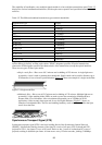
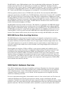
MGX 8800 Series Wide−Area Edge Switches
The MGX 8800 series is the newest line of WAN switches. It is designed as an edge device to connect
narrowband traffic to broadband. The capability of the switch enables you to move it closer to the core. It has
the greatest flexibility of all the WAN switches. It has 32 single−height (16 double−height) module slots. Two
of the double−height slots are reserved for redundant processor switch modules, 4 single−height slots are
reserved for optional value−added service resource modules, and 24 single−height slots are reserved for
interface modules.
The throughput can scale from 1.2Gbps to 45Gbps. A route processor module can be added for Layer 3
functionality (a Cisco 7200 series router in a single double−height module). The network interfaces range
from Ethernet, Fiber Distributed Data Interface (FDDI), and channelized T1 to OC−48c. A Voice
Interworking Service Module (VISM) can be added to terminate T1/E1 circuits. Each module has 8 T1/E1
interfaces, and up to 24 modules can be added to the chassis (a total of 4,608 voice calls for T1 and 6,144
voice calls for E1). The VISM provides toll−quality voice services. All the packetization and processing are
handled by the module. It supports echo canceling, voice compression, silence suppression, VoIP/VoATM,
auto fax/modem tone detection, and more.
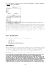
WAN Switch Hardware Overview
Cisco WAN switches have a wide range of capabilities and features. Physically, they share many common
characteristics. All the WAN switches are designed to have a minimum 99.999 percent service availability
when configured properly—that is, 5.256 minutes of downtime in 1 year of continuous operation. Each
component can have a hot standby to act as a failsafe. All the components are hot swappable, and all the
chassis have redundant power feeds.
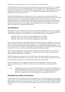
For ease of replacement and upgrades, all the modules consist of a front card and a back card. The front card
contains the intelligent part of the card set: the processor, memory, storage, control button, and other
components. The back card contains the Physical layer component. If there is no backplane for the set, a blank
faceplate is used. This system enables the quick replacement/upgrade of the front card without distributing the
physical connections. The front card and back card are connected to a system bus backplane when inserted.
59